
Air-bag suspension system

a suspension system and airbag technology, applied in the direction of shock absorbers, foldable cycles, transportation items, etc., can solve the problems of frequent replacement, and achieve the effect of preventing bottoming out and being easily exchangeabl

Inactive Publication Date: 2005-06-14
AFCO PERFORMANCE GRP LLC
View PDF28 Cites 26 Cited by
  • Summary
  • Abstract
  • Description
  • Claims
  • Application Information

AI Technical Summary

Benefits of technology

[0007]An air-bag suspension system for a motorcycle having a main frame, a pair of fender struts mounted to the main frame in a parallel fashion, and a swing arm pivotally mounted to the motorcycle main frame about a pivot axis. The air-bag suspension system includes an on-board compressor, a solenoid valve, at least one or two shock absorber assemblies each having an internal air-bag, and a plurality of air hoses and Y-connectors. The swing arm includes a pair of arms which include mounting brackets to accommodate the lower ends of the shock absorber assemblies. The air-bag suspension system allows the rider to remotely raise and lower the rear end of the motorcycle while in use by increasing or decreasing the air in the air-bags and provides a broad range of adjustment to accommodate heavy loads, bottoming-out, road hop and desirable aesthetic characteristics. The air is generated by the on-board compressor and released by the solenoid valve. There is also provided an optional pressure gauge which allows the rider to monitor the amount of air in the air-bags at all times. When properly adjusted, the air-bag suspension system provides a smoother ride with greater wheel travel than that provided by stock suspension systems.

Problems solved by technology

The coil spring hydraulic suspension utilizes an air-assist suspension system which only allows minimal adjustment (approximately 15-35 psi), which provides minimal wheel travel which causes bottoming out, and which requires frequent replacement due to seal and overall shock failure.

Method used


Image

  • Air-bag suspension system
  • Air-bag suspension system
  • Air-bag suspension system

Examples


Embodiment Construction

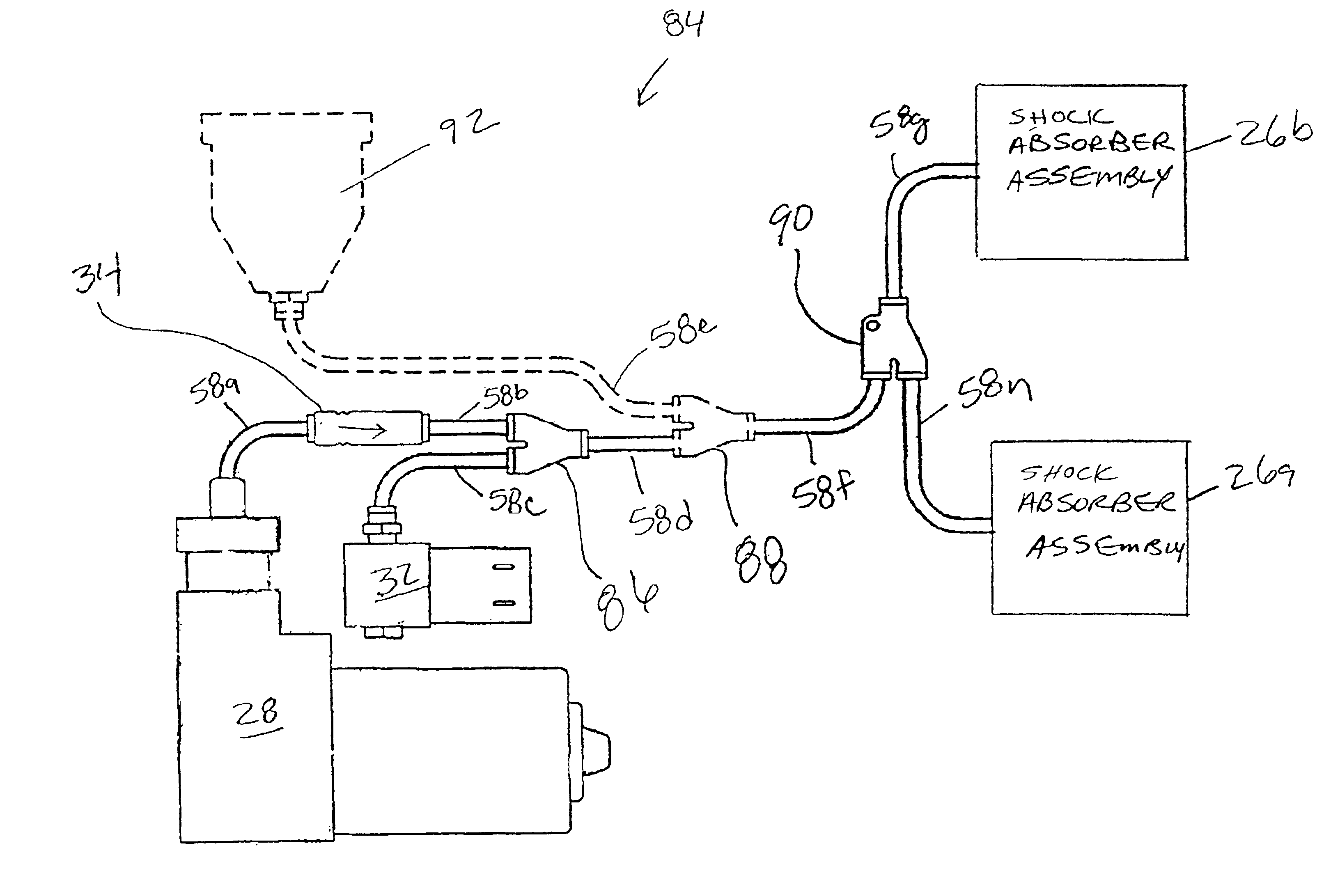
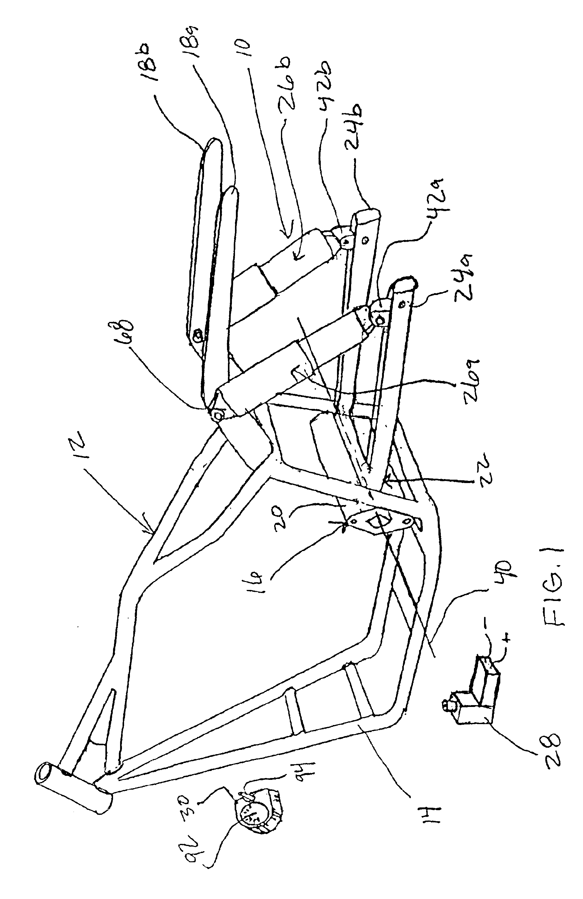
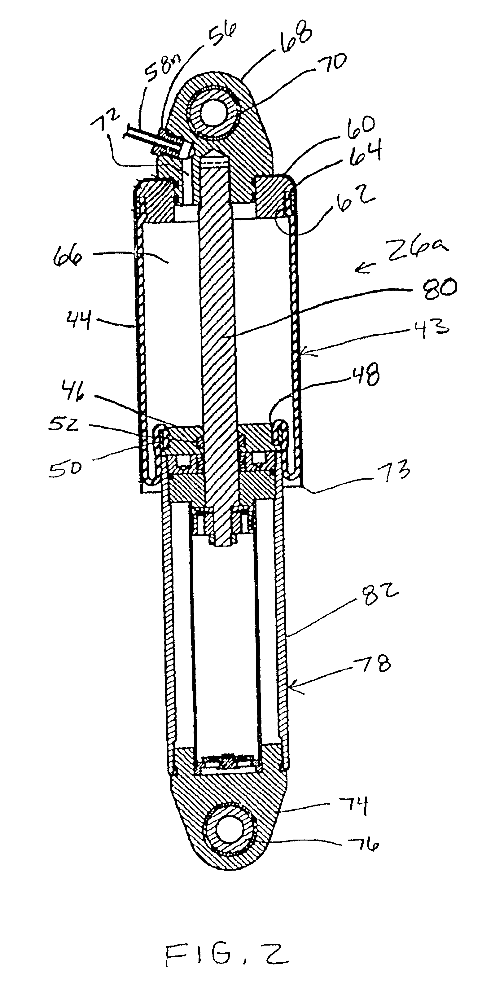
[0032]FIG. 1 illustrates an isometric view of the air-bag suspension system 10, the present invention, mounted to a representative motorcycle chassis 12. The chassis 12 is comprised of a main frame 14, a swing arm assembly 16 which is appropriately mounted to the main frame, and a pair of fender struts 18a and 18b. The swing arm assembly 16 is comprised of swing arm pivot assembly 20 and a swing arm 22 having a pair of arms 24a and 24b. The construction and function of the swing arm assembly 16 is understood by anyone skilled in the art. The air-bag suspension system 10 is comprised of shock absorber assemblies 26a and 26b, an on-board compressor 28, a solenoid valve 32 (shown in FIGS. 7 and 8), a control panel 30 having a pressure gauge 92 and a switch 94, and a plurality air hoses 58a-58n and Y-connectors 86, 88 and 90, as illustrated in FIG. 7. The control panel 30 may be mounted on the handlebars, the gas tank, the main frame 14 or any other appropriate position where the rider ...


PUM


Abstract

An air-bag suspension system for a motorcycle having a motorcycle main frame, fender struts extending outwardly from the main frame, and a swing arm pivotally mounted to the main frame about a pivot axis. The air-bag suspension system includes shock absorber assemblies each having an air-bag. The air in the air-bags is generated by an on-board compressor and released through a solenoid valve. The air-bag suspension system replaces the standard coil spring hydraulic suspension commonly found on motorcycles and provides a greater range of adjustment, remotely controlled, while the motorcycle is in use. The air-bag suspension system accommodates heavier loads than the stock suspension systems when the air-bags are fully inflated; and when deflated completely, provide an aesthetically pleasing stance. The range of wheel travel provided allows the rider to adjust the suspension to provide the smoothest ride coupled with an increased load capacity or adverse road conditions.

Description

CROSS REFERENCES TO CO-PENDING APPLICATIONS[0001]This application is a continuation-in-part (CIP) of Ser. No. 09 / 753,591 entitled “Air-Bag Suspension System” filed on Jan. 3, 2001, now abandoned both by the same inventor, pending.BACKGROUND OF THE INVENTION[0002]1. Field of the Invention[0003]The present invention is for an air-bag suspension system for a motorcycle or other vehicle which utilizes an on-board compressor to increase the pressure in the air-bags and a controlled release valve for decreasing the pressure in the air-bags. The air-bag suspension system replaces the standard coil spring hydraulic shock system currently and previously used on most motorcycle rear suspension systems. The air-bag suspension system creates a greater range of wheel travel which allows the user to raise or lower the rear end of the motorcycle remotely and while traveling to accommodate for motorcycle load, rear fender ground clearance, road conditions and desired appearance.[0004]The present in...

Claims


Application Information

Patent Timeline
IPC IPC(8): B60G17/04B60G15/14B60G15/00B60G17/052F16F9/02F16F9/04F16F7/00F16F9/32
CPCB60G15/14B60G17/0521F16F9/3207F16F7/00F16F9/0472B60G2202/314B60G2202/412B60G2202/32
Inventor JURRENS, JESSE A.
Owner AFCO PERFORMANCE GRP LLC
Learn More