Turbine

Inactive Publication Date: 2005-06-14
HOLSET ENG CY LTD
View PDF23 Cites 30 Cited by
  • Summary
  • Abstract
  • Description
  • Claims
  • Application Information

AI Technical Summary

Benefits of technology

[0007]In embodiments of the present invention, the driving effect of the bearing adjacent the turbine end of the shaft is used to maintain the rotational speed of the more highly directionally loaded gear at the other end of the shaft. As a result, when high gear loads are applied to the shaft, the bearing at the end of the shaft remote from the turbine is prevented from slowing and losing load carrying capacity by driving torque which is delivered from the less directionally loaded bearing at the end of the shaft adjacent the turbine.
[0008]The driving effect at the gear end of the bearing is produced by modifying the relative surface areas and operating

Problems solved by technology

This external force significantly increases the load, particularly on the bearing closest to the gear.
As a result conventional floating bearing arrangements are not suitable for use at the gear end (or other drive connection) of a power turbine.
However, the directional loa

Method used


Image

  • Turbine
  • Turbine
  • Turbine

Examples


Embodiment Construction

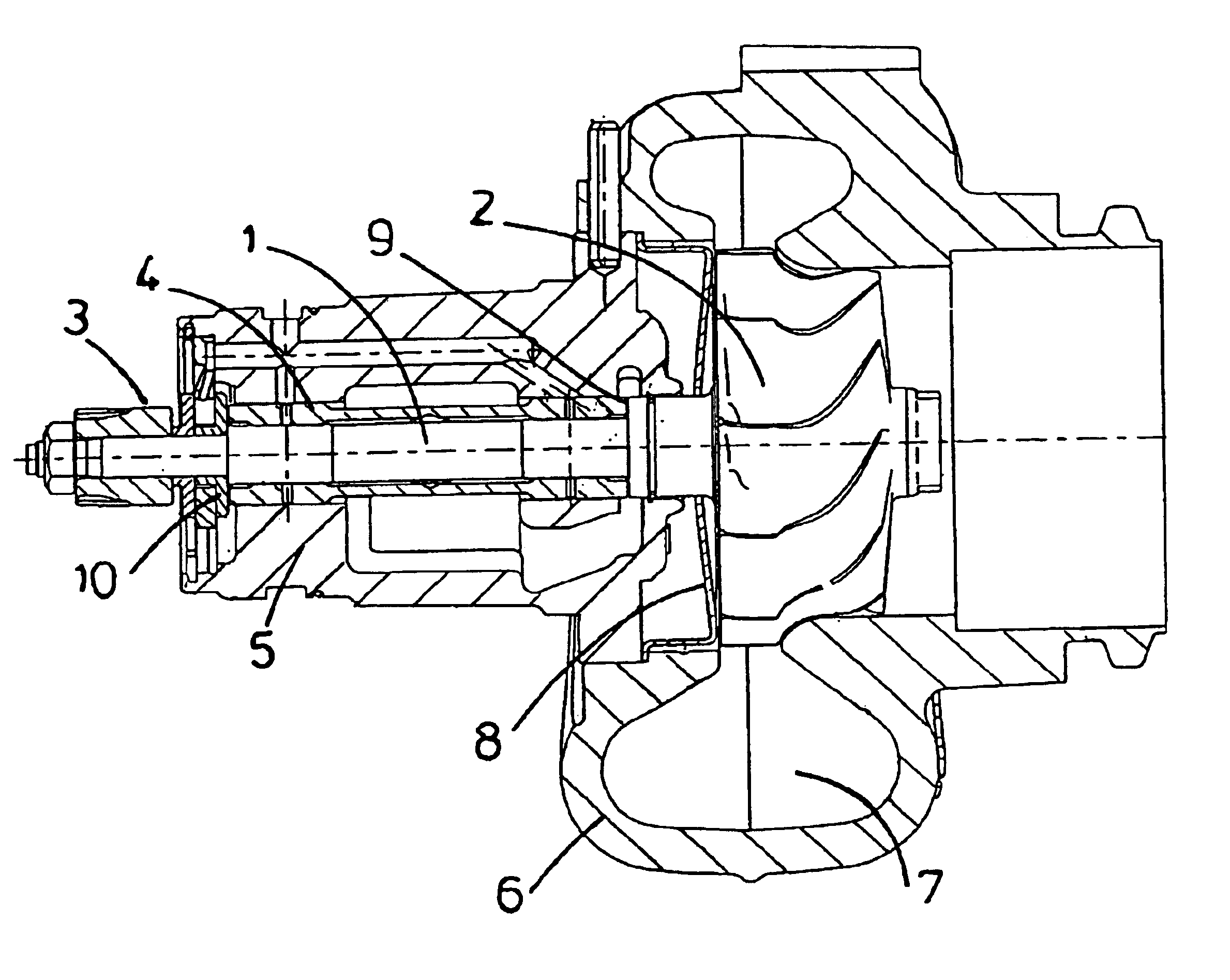
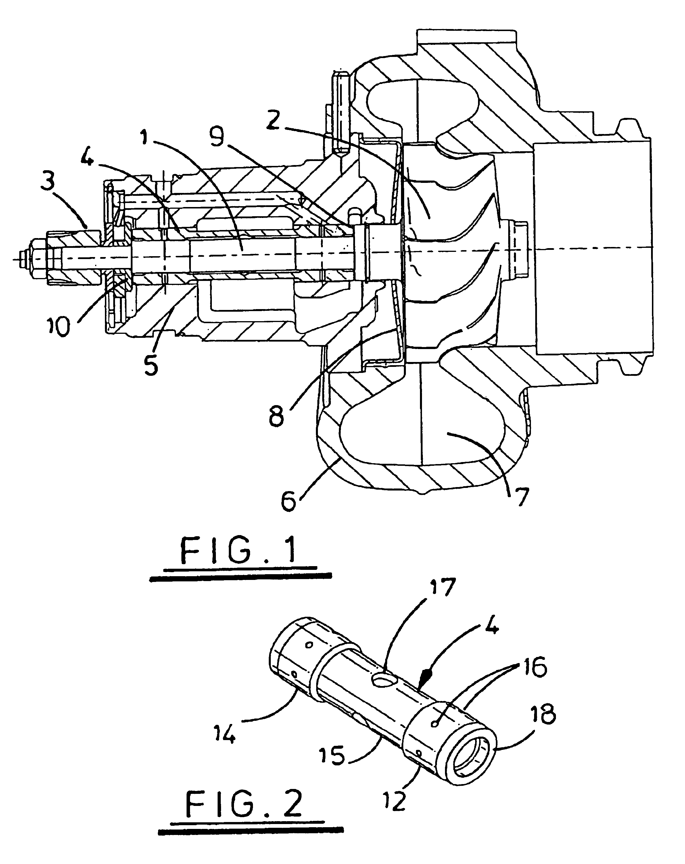
[0019]Referring to FIG. 1, the illustrated turbocharger comprises a shaft 1 which supports at one end a turbine 2 and supports at the other end a drive gear 3. The shaft 1 is supported in a one piece tubular bearing 4 which is supported within a housing 5. The housing 5 is secured to a body 6 which defines a volute 7 through which exhaust gases delivered from an internal combustion engine pass to apply torque to the turbine 2. A heat shield 8 protects the bearing assembly from the hot gases which drive the turbine 2.

[0020]One end of the bearing 4 abuts a shoulder 9 defined by the shaft whereas the other end of the bearing 4 abuts a flange 10 which forms part of a thrust bearing which maintains the axial position of both the bearing 4 and the shaft 1. Flange 10 is part of an integral sleeve 11a telescoped over an integral extension 1a of shaft 1. A second flange 10a is also telescoped over extension 1a, as is the gear 3. A nut 3a sandwiches gear 3 and flanges 10, 10a to capture, with...


PUM


Abstract

A turbocharger in which a drive shaft supports at one end a turbine driven by exhaust gases from an internal combustion engine. The end of the drive shaft remote from the turbine supports a drive connection which is coupled to an output shaft of the driving engine. The shaft is supported in a housing by a first bearing adjacent the turbine and a second bearing adjacent the drive coupling. The first and second bearings each define an inner bearing surface relative to which the shaft rotates and an outer bearing surface which rotates relative to the housing. The first and second bearings are mechanically coupled together such that they rotate relative to the housing at the same speed. Coupling the two bearings together ensures that directional forces applied to the bearing at the end adjacent the drive connection which might cause that bearing to seize are resisted by torque delivered from the bearing at the other end of the shaft.

Description

FIELD OF THE INVENTION[0001]The present invention relates to a turbine, and in particular to a power turbine of the type found in turbocompound engines.BACKGROUND OF THE INVENTION[0002]A turbocharger comprises a drive shaft one end of which supports a turbine arranged to be driven by exhaust gases from an internal combustion engine. In automotive heavy duty diesel engines turbocharger shafts are supported in a housing usually by two separate floating bearings which are retained in position by circlips or some other conventional mechanical configuration. In a fully floating bearing, the shaft rotates relative to an inner bearing surface defined by a bearing body which also defines an outer bearing surface which itself rotates relative to a surrounding housing. The turbocharger shaft is generally located axially by a separate bearing. In a turbocharger the end of the shaft remote from the turbine simply drives a compressor which is used to deliver air to the engine.[0003]In turbocompo...

Claims


Application Information

Patent Timeline
IPC IPC(8): F01D25/16F16C17/18
CPCF01D25/164F16C17/18F01D25/166F16C2360/24F16C17/02
Inventor PARKER, JOHN FREDERICKBILLINGTON, ANTHONY
Owner HOLSET ENG CY LTD
Why Eureka
Try Eureka