
Scalable liquid distribution system for large scale chromatography columns

Inactive Publication Date: 2005-06-14
GE HEALTHCARE BIO SCI CORP
View PDF13 Cites 22 Cited by
  • Summary
  • Abstract
  • Description
  • Claims
  • Application Information

AI Technical Summary

Benefits of technology

[0019]One advantage with such a liquid distribution system is that it provides excellent distribution characteristics.
[0021]Still a further advantage is that the proposed liquid distribution system reduces the risk for sanitary problems, due to the simple design comprising few interconnected elements.
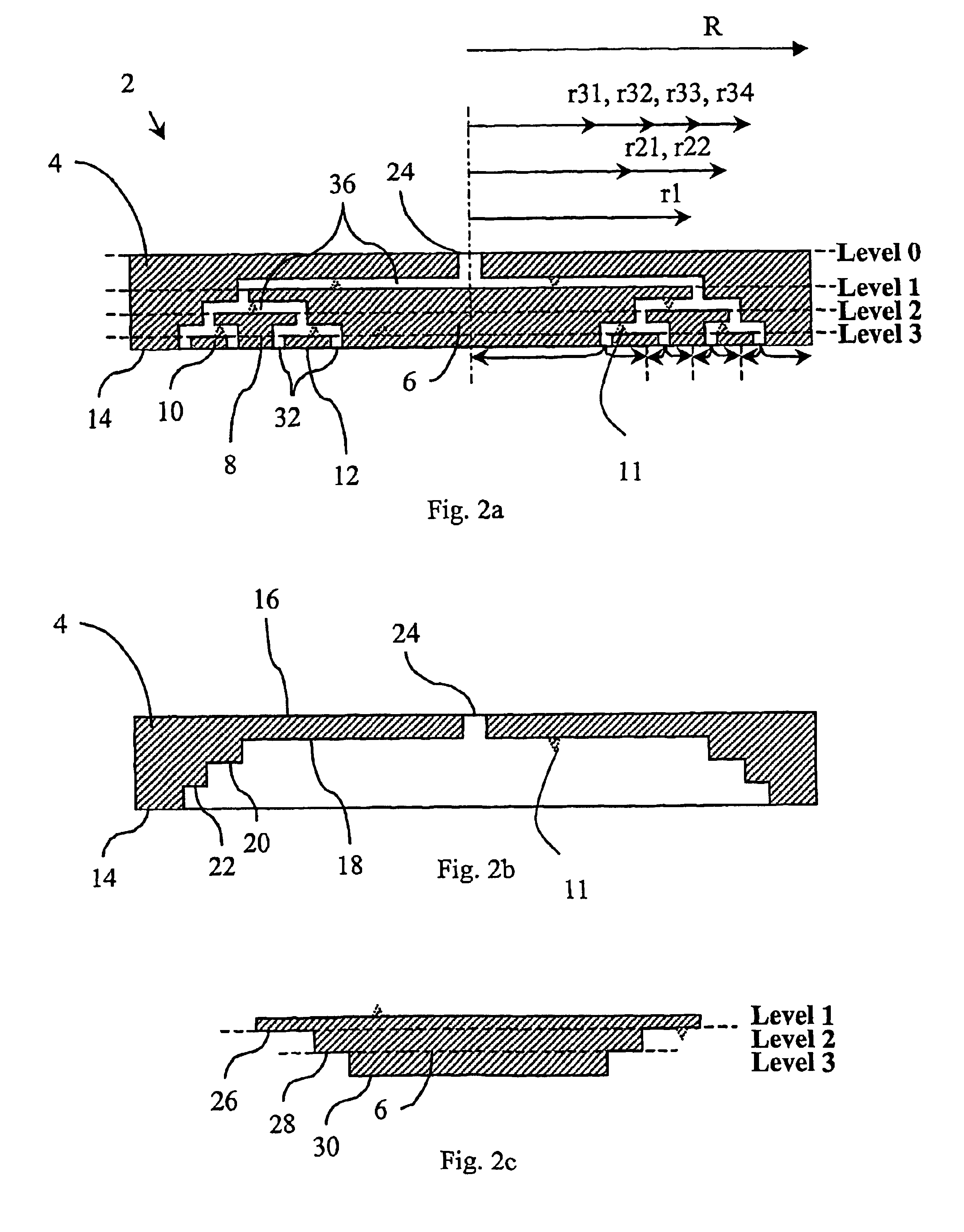
[0023]Still a further advantage is that the proposed liquid distribution system is scalable by adjusting the number of pre-distribution levels (0,1,2,3 . . . ) at a given column diameter and by adjusting the geometry of the fluid paths (channel height) at a given pre-distribution level.

Problems solved by technology

Among these problems are (a) non-uniform initial fluid distribution at the top of the packing as well as non-uniform fluid collection at the outlet of the packing and (b) “channelling”, which is described by a non-uniform flow field within a packing, typically caused by pressure gradients that are perpendicular to the mean direction of velocity due to pressure loss in the fluid distribution system.
Whenever the pressure drop through the column is high relative to the pressure drop in the distributor, however, the fluid tends to channel in the centre of the column causing excessive dispersion.
This severely limits the effectiveness of chromatographic separations and is particularly acute for large diameter columns.
The problem of non-uniform initial fluid distribution refers generally to the problem of applying a sample volume simultaneously over the cross-sectional area of the packing.
Without a simultaneous introduction of fluid in the plane defined by the top of the packing, it is virtually impossible to achieve a distinct movement of a sample zone or front through the packing.
Both problems will lead to increased dispersion in the chromatographic system by broadening the convective residence time distribution of a tracer substance transported with the fluid throughout the system.
In theory and from experience it is known that such a system deteriorates in performance with increasing diameter of the column.
This difference in residence time is enlarged with column diameter and leads to chromatographic band broadening which becomes most severe with small particles.
This problem corresponds to the non-uniform initial fluid distribution.
Multiple inlets reduce the residence time differences but are expensive to produce.
A drawback of the plate system is that the spacing and size of the openings in the plate must be calculated for any particular fluid according to its viscosity and other physical characteristics (the rheology of the fluid) so that the system will work properly with that particular fluid at a particular flow rate.
A drawback to the plate system, however, is that variation in the fluid being distributed or the flow rate will affect the uniformity of the distribution.
Although this system provides excellent distribution, it suffers from several disadvantages, especially in that it is difficult to produce especially for a large number of channels at large column diameters.
There is further a risk for sanitary problems due to the troublesome cleaning of such a large amount of channels of such small size, and in that it is impossible to prevent fluid from entering in between the two layers.
Due to the modular construction this system may be produced using large-scale production techniques, but the high grade of complexity still results in high production costs.
Like the layered distribution structure, complex systems of this type are extremely difficult to clean; whereby there is an obvious risk for sanitary problems.
Another problem is that excising techniques makes it difficult to upscale from laboratory columns (small diameter) to production columns of large diameter, as it is extremely difficult to forecast the distribution characteristics.
Furthermore, it is difficult and expensive to alter the distribution characteristics of such systems.
To date, no distribution system is available which meets this end.

Method used


Image

  • Scalable liquid distribution system for large scale chromatography columns
  • Scalable liquid distribution system for large scale chromatography columns
  • Scalable liquid distribution system for large scale chromatography columns

Examples


Embodiment Construction

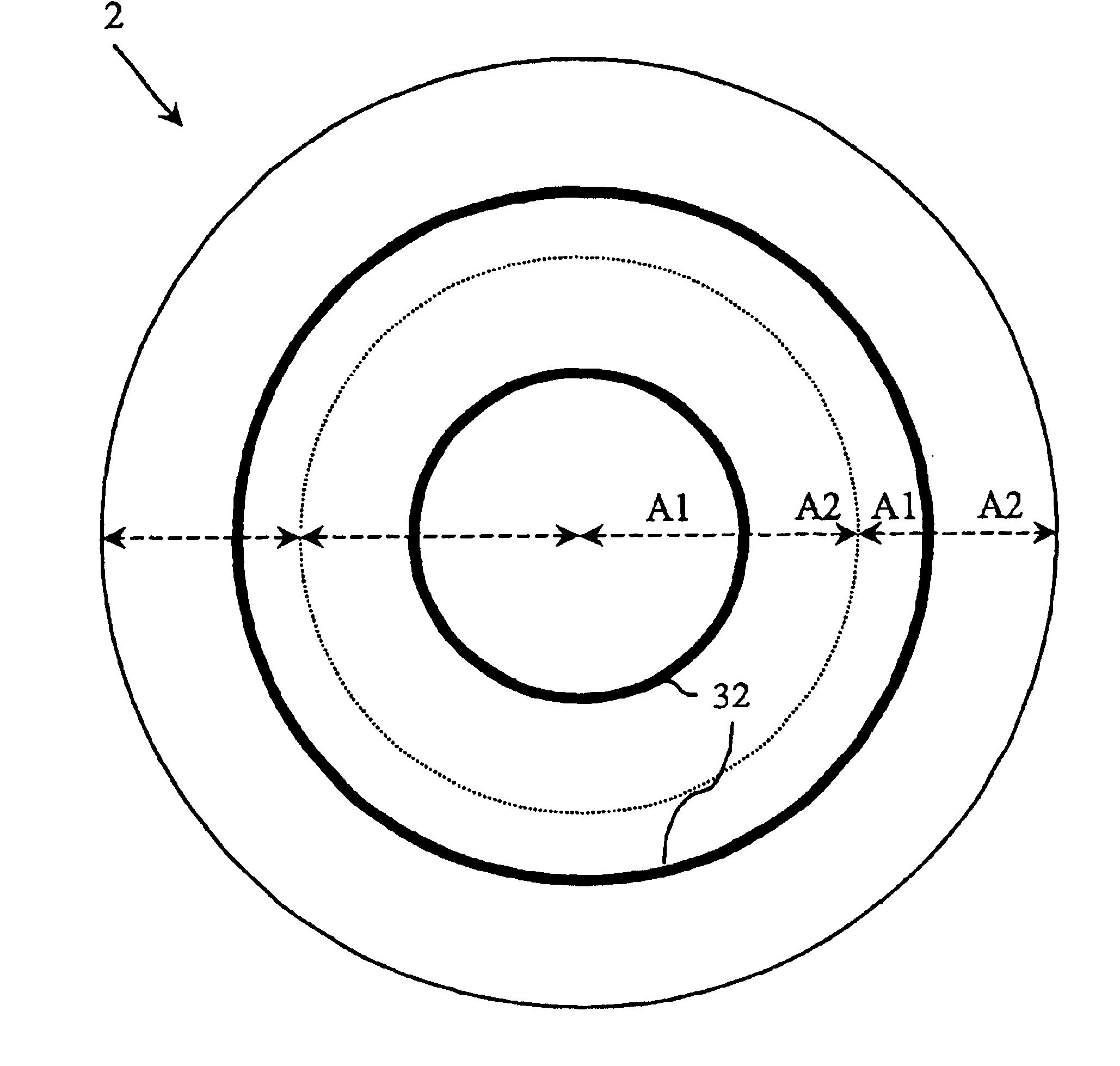
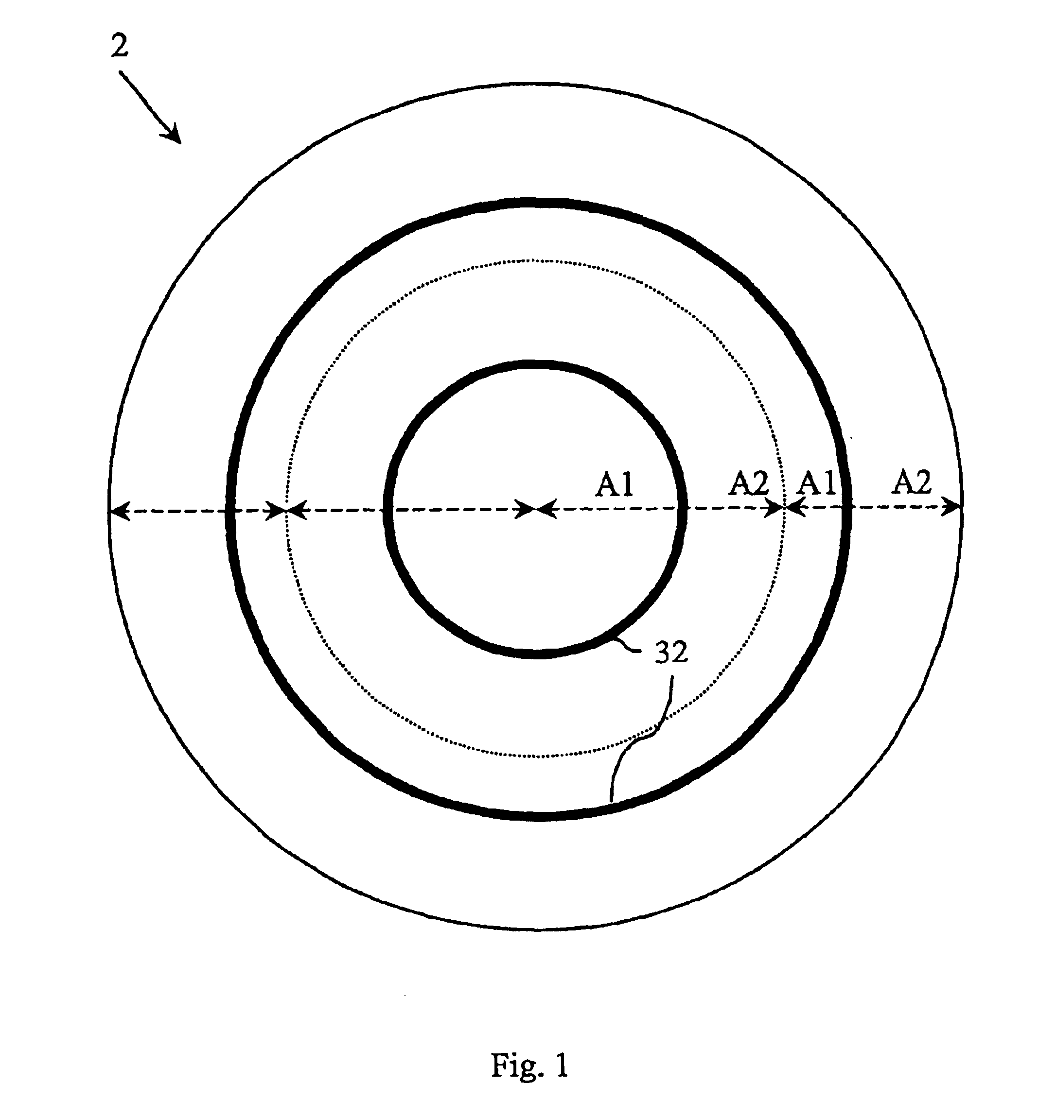
[0037]The present invention disclose a uniform fluid distribution system 2 for use with a liquid transfer system for maintaining an interface between liquid phases within a large scale separator system including a cell of circular cross-section. Into which cell, liquid may be introduced as discrete phases via the distribution system 2 to an inlet zone occupying a first approximately transverse cross-sectional region of said cell whereby a discrete liquid phase plug is developed. Thereafter the discrete liquid phase plug migrates approximately longitudinally in a direction normal said first cross-sectional region towards an outlet zone occupying a second approximately transverse cross-sectional region of said cell. Generally, the distribution system 2 comprises at least one liquid inlet and at least two distribution outlets, which are connected by an internal flow connection system.

[0038]Basically, the present invention describes the idea of pre-distributing a fluid by subdividing a ...


PUM

PropertyMeasurementUnit
Flow rateaaaaaaaaaa
Ratioaaaaaaaaaa
Radiusaaaaaaaaaa

Abstract

A uniform fluid distribution system (2) for use with a liquid transfer system (100) for maintaining an interface between liquid phases within a large scale separator system including a cell into which liquid may be introduced as discrete phases at an inlet zone occupying a first approximately transverse cross-sectional region of said cell and outputted at an outlet zone occupying a second approximately transverse cross-sectional region of said cell. Said distribution system comprises at least one liquid inlet (24) and at least two distribution outlets (32), which are connected by an internal flow connection system (36). Wherein said distribution outlets (32) are formed as concentric annular or rectilinear distribution-slots (32), each with an unique radius / distance to the midpoint r to the midpoint between an inner slot-radius / distance to the midpoint and an outer slot-radius / distance to the midpoint, said radii / distances to the midpoint defining a slot-width w, through which annular distribution-slot (32) liquid entering said inlet (24) is distributed to said cell along an approximately horizontal plane, and said internal flow connection system (36) is formed such that it provides an essentially uniform fluid flow through the distribution-slots (32).

Description

CROSS REFERENCE TO RELATED APPLICATION[0001]This application is a filing under 35 U.S.C. §371 and claims priority to international patent application number PCT / EP02 / 05145 filed May 10, 2002, published on Nov. 21, 2002 as WO02 / 092188, and to foreign application number 0111485.9 filed in Great Britain on May 11, 2001, the entire disclosures of which are hereby incorporated by reference.FIELD OF THE INVENTION[0002]The present invention relates to a liquid distribution system for chromatography columns. More specifically, the invention relates to a scalable liquid distribution system for large-scale chromatography columns.BACKGROUND OF THE INVENTION[0003]In separation procedures, particularly in liquid chromatography, the fluid distribution system is critical to the overall performance, and becomes more so as the cross-section of the chromatographic column increases.[0004]Columns used in liquid chromatography typically comprise a body-forming structure enclosing a porous media through ...

Claims


Application Information

Patent Timeline
IPC IPC(8): B01D15/10B01D15/14B01D15/16
CPCB01D15/14B01D15/16G01N30/6017Y10T137/2224
Inventor GEBAUER, KLAUS
Owner GE HEALTHCARE BIO SCI CORP
Learn More