Process for loading a reactor

Inactive Publication Date: 2005-06-14
CLEAN HARBORS CATALYST TECH
View PDF8 Cites 24 Cited by
  • Summary
  • Abstract
  • Description
  • Claims
  • Application Information

AI Technical Summary

Benefits of technology

[0010]The present invention provides a loading device for distributing solid particles into a multi-tube reactor in which the reactor tubes are substantially vertical and held together by an upper and a lower tube sheet, the loading device comprising a plurality of adjacent polygonal, i.e. triangular, quadrangular or hexagonal, plates, each polygonal plate having fr

Problems solved by technology

The loading or re-loading of the multitude of narrow and elongated reactor tubes with catalyst, the particles of which are generally not very much smaller than the inner diameter of the tubes, is difficult and time-consuming.
An even distribution of the catalyst particles inside each tube and between all tubes is very important but difficult to achieve.
Such a procedure is unacceptable today because of the large numbe

Method used


Image

  • Process for loading a reactor
  • Process for loading a reactor

Examples


example

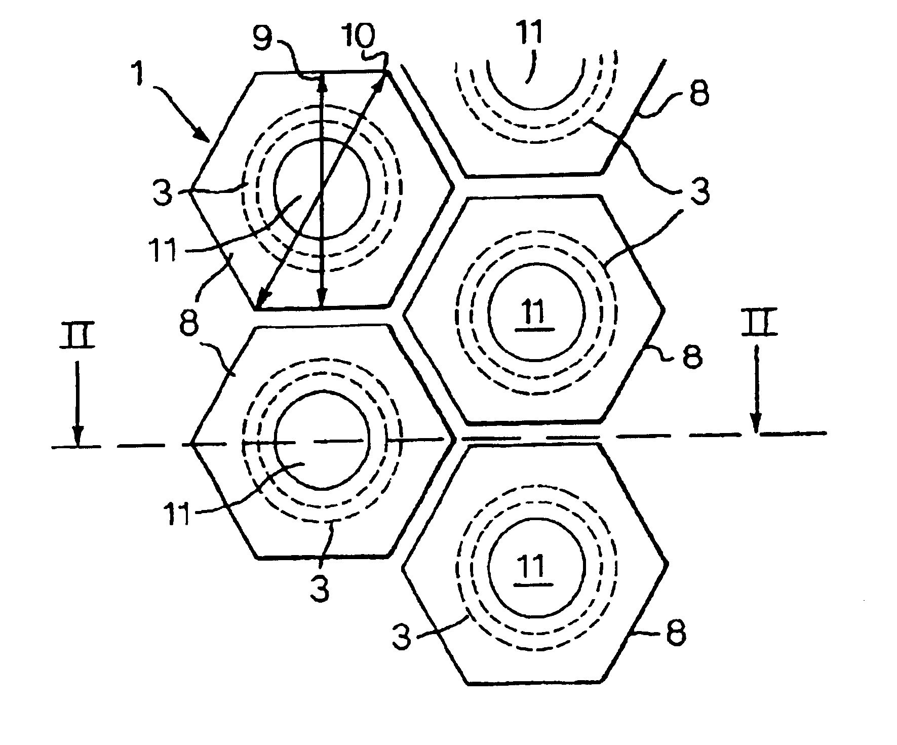
[0031]Four chemical reactors, each comprising about 3000 vertical reactor pipes, each reactor pipe having an outer diameter of 45.2 mm, an inner diameter of 39.2 mm, and a length of 12.8 m, the distance between neighbouring pipes being 63 mm, were loaded with catalyst particles having the basic shape of a cylinder with a diameter of 8 mm and a length of 8 mm.

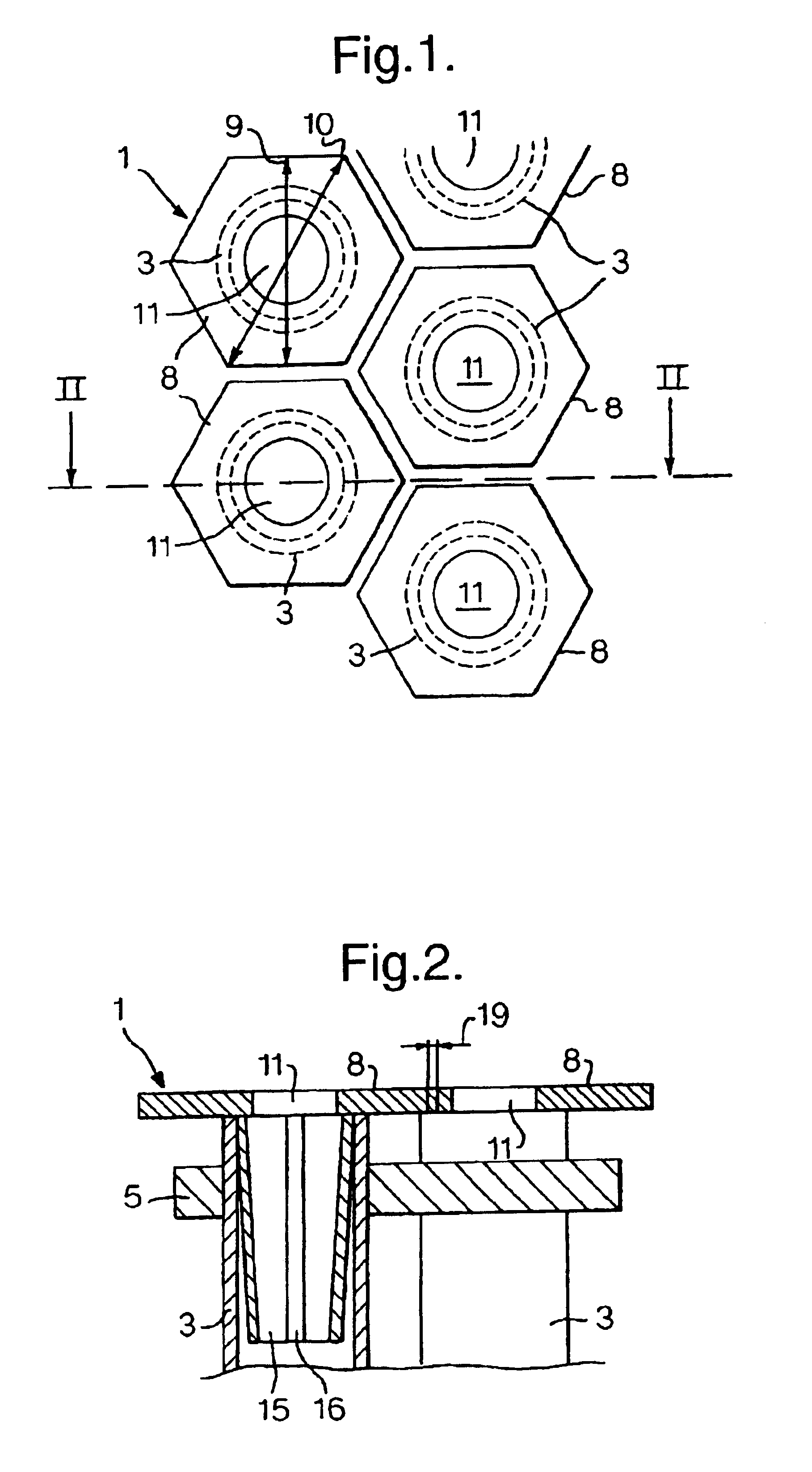
[0032]Loading devices were used, each of which was made of polypropylene and consisted of a multitude of hexagonal plates. Each hexagonal plate was 59.0 mm across the minor axis and 69.0 mm across the major axis, with a thickness of 5.0 mm, and had a single central hole of 23.8 mm ({fraction (15 / 16)} inches) in diameter, and a slotted insert extending at a right angle from the edge of the hole. Each insert was in the form of a tapered pipe 30.0 mm in length, 39.0 mm outside diameter, 35.0 mm inside diameter tapering to 38.0 mm outside diameter and 35.0 mm inside diameter, and had a compression slot 3 mm wide extending the full l...


PUM

PropertyMeasurementUnit
Fractionaaaaaaaaaa

Abstract

There is provided a method for loading solid particles into a multi-tube reactor having an upper tube-sheet holding together the upper ends of the multitude of reactor tubes, the method comprising positioning a loading device having a plurality of holes on top of the upper tube-sheet such that the loading device rests on and substantially covers the upper tube-sheet and the holes correspond to the reactor tubes, the loading device comprising a plurality of adjacent polygonal plates, each polygonal plate having from 1 to 30 holes, each hole corresponding to one reactor tube; pouring the particles over the combined polygonal plates covering the tube-sheet; sweeping the particles through the holes in the plates into the respective reactor tubes; removing residual particles and any dust remaining on and between the plates; and removing the loading device.

Description

[0001]This application is a divisional of patent application Ser. No. 09 / 309,924, filed May 11, 1999, now U.S. Pat. No. 6,409,977.FIELD OF THE INVENTION[0002]This invention relates to a method of loading a multi-tube reactor with solid particles, in particular catalyst particles.BACKGROUND OF THE INVENTION[0003]A so-called multi-tube reactor is in essence a shell-and-tube exchanger containing up to several thousands or even tens of thousands of substantially vertical reactor tubes inside its shell, each reactor tube containing a fixed bed of catalyst particles and being cooled externally by a fluid circulating between the tubes in the shell. Multi-tube reactors are used for highly exothermic reactions, such as the epoxidation of ethylene. While the cross-sections of the reactor tubes are relatively small (such as 20-50 mm), their length is great (such as 1.5 to 20 m). Inside the reactor shell, the reactor tubes are held together by an upper and a lower tube sheet. Above the tube she...

Claims


Application Information

Patent Timeline
IPC IPC(8): B01J8/02B01J8/00B01J8/06B01J8/04B01J10/00
CPCB01J8/003B01J8/06B01J2208/00769B01J2208/00752
Inventor HARPER, JAMIE STEWARTTHEW, KARL BARRY
Owner CLEAN HARBORS CATALYST TECH
Why Eureka
Try Eureka