Method and device for heating preform

Inactive Publication Date: 2005-06-14
YOSHINO KOGYOSHO CO LTD
View PDF10 Cites 0 Cited by
  • Summary
  • Abstract
  • Description
  • Claims
  • Application Information

AI Technical Summary

Benefits of technology

[0016]As mentioned above, since the heating of the preform by the heat sources is accomplished in the state where the heating of the outer surface of the preform is suppressed, as a whole preform, it is quickly heated by the high power of the heat sources in a state where a temperature rising speed of the outer surface is slightly suppressed. However, since the heat sources are in the high power state, the blow-out of the cooling air to the preform not only suppresses the temperature rising speed of the outer surface of the preform but also prevents the occurrence of a problem such as carbonization or the like due to the overheat of the outer surface of the preform.
[0020]According to the invention of Claim 1 as mentioned above, since the preform is heated while the outer surface portion of the preform which is heated strongest is cooled by the first heating process, the quick heating can be sufficiently performed to the preform without overheating. Thus, the heating time of the preform can be remarkably reduced. After the difference between the outer surface temperature and the inner surface temperature of the preform which is caused by the first heating process is corrected and restricted within the predetermined range by the temperature adjusting process, the second heating process is performed while blowing the cooling air in a manner such that the preform is set to the constant temperature distributing pattern and the temperature difference between the outer surface and the inner surface of the preform is not increased. Thus, the preform can be heated in accordance with the set temperature distribution in a state where the temperature difference between the outer surface and the inner surface of the preform which is biaxially stretched and blow molded into the bottle shape is certainly positioned within the proper range.
[0025]In the first zone, the preform which is revolving and move along the conveying path is subjected to the first heating process such that the heating process by the heat sources is executed from one side of the conveying path and, at the same time, the cooling process by the cooling air is executed from the other side as an opposite side of the conveying path, so that the heat sources are set to the high power state without setting the outer surface portion of the preform into the overheating state, thereby accomplishing the quick heating of the preform.
[0027]In the third zone, there is executed the second heating process such that the heating process of the constant temperature distribution by the heat sources is executed from one side of the conveying path and, at the same time, the cooling process to suppress a temperature rising degree on the outer surface side of the preform is executed by the cooling air from the other side as an opposite side of the conveying path. Thus, the preform is heated in accordance with the set temperature distribution without increasing the temperature difference between the outer surface side and the inner surface side of the preform.
[0031]In the invention of Claim 5, the light from the heat sources which penetrated the conveying path can be reflected by the panel for blowout ports and irradiated to the preform without being irradiated to the preform, so that heating efficiency of the preform by the heat sources is improved.

Problems solved by technology

According to the method of heating the preform by the heat transfer from the atmosphere temperature, since a coefficient of thermal conductivity of the PET material is slightly lower, it takes a long time to heat the whole preform including an inner surface to a desired temperature.
However, even if the near infrared heaters are used as heating sources of the preform or another proper heat source (for example, a sheath heater or the like) is used, since the preform is heated from its outside, the following problem exists.
Thus, heating time of the preform cannot be sufficiently shortened.
Such a technique, however, has the following problem.
That is, since both of those means have to be made operative almost simultaneously, the heating time cannot be sufficiently shortened.
Further, since heating equipment is large in size and complicated, a large installing space and the expensive cost of equipment are necessary.

Method used


Image

  • Method and device for heating preform
  • Method and device for heating preform
  • Method and device for heating preform

Examples


Embodiment Construction

[0041]An embodiment of the invention will be described hereinbelow with reference to the drawings.

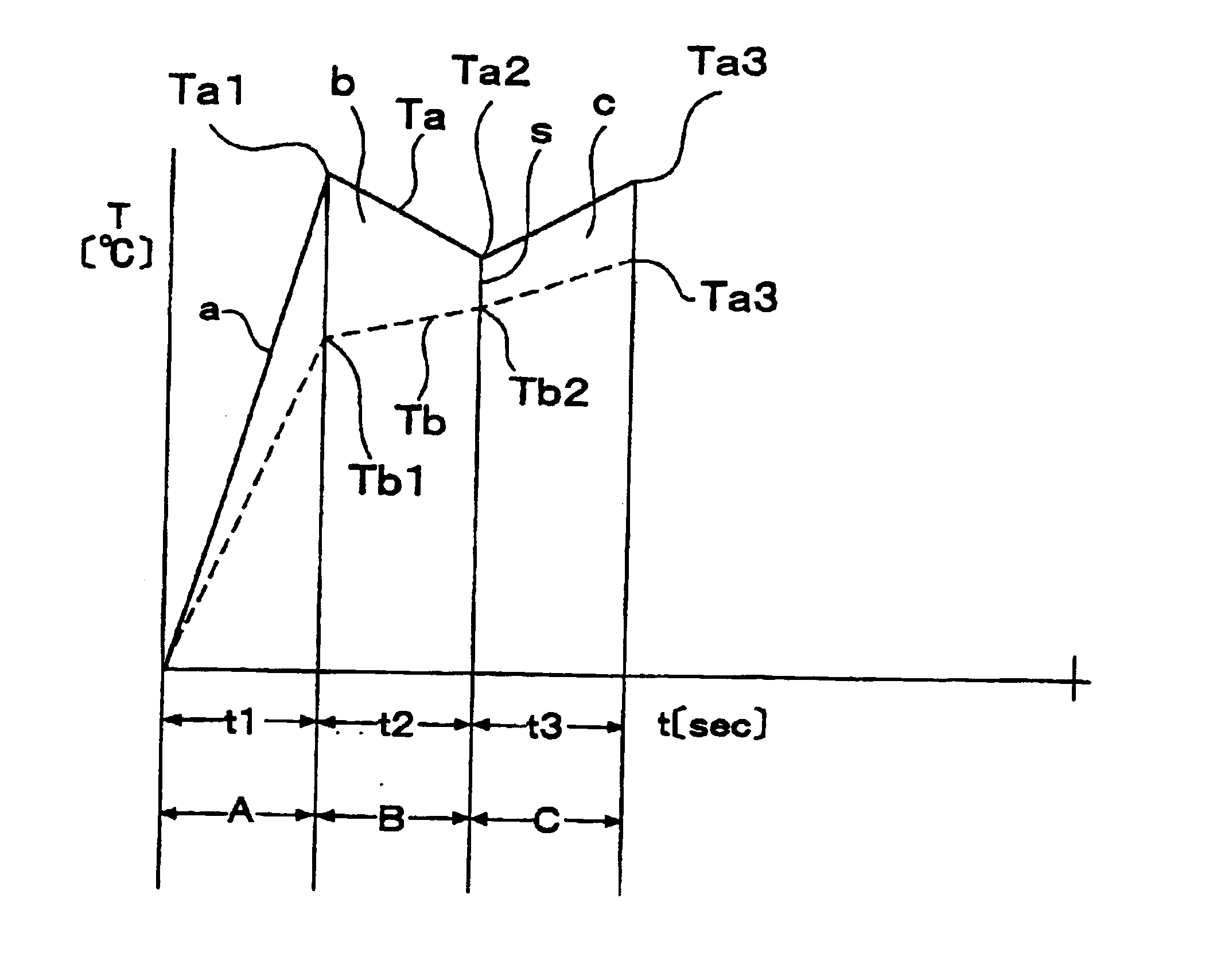
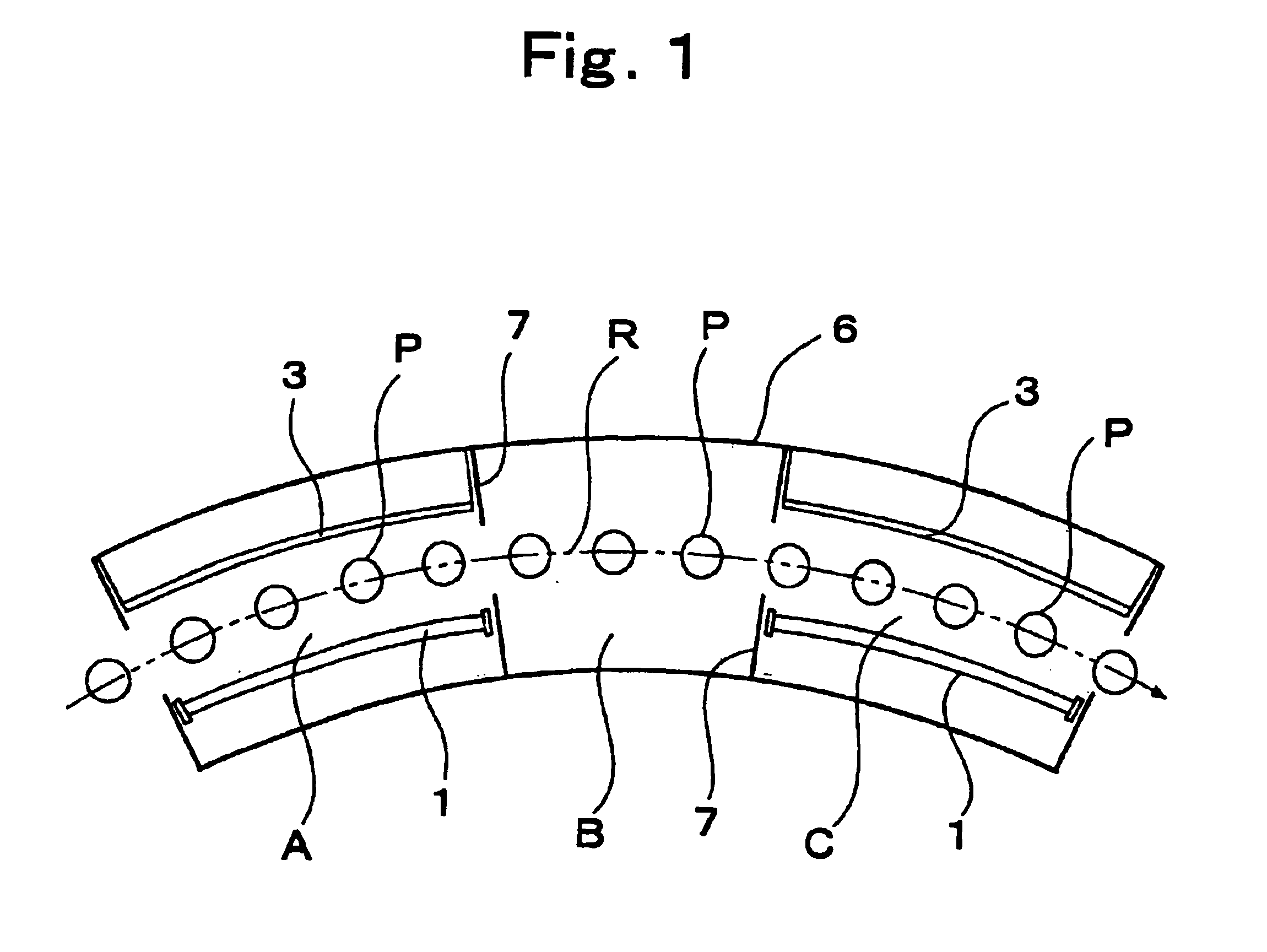
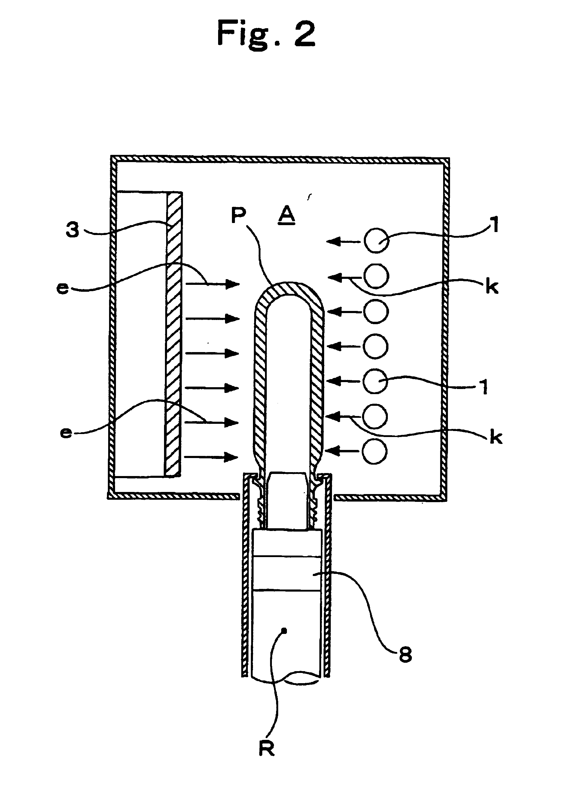
[0042]FIGS. 1 to 6 show the embodiment of a device of the invention. The device is formed by a turntable, a chain, and the like. A long rectangular cylindrical outer shell 6 made of a heat resisting material is arranged along a conveying path R for conveying a preform P held to a mandrel 8 in a headstanding posture while revolving the preform together with the mandrel 8 so as to surround the conveying path R. The inside of the outer shell 6 is divided by partitions 7 made of a heat resisting material in order of a first zone A, a second zone B, and a third zone C from the upstream side of the conveying path R (refer to FIG. 1).

[0043]The first zone A (refer to FIGS. 1, 2, and 5) is constructed as follows. Near infrared heaters serving as a plurality of heat sources 1 extending along the conveying path R are arranged on one side of the conveying path R in parallel along the axial center d...


PUM

PropertyMeasurementUnit
Temperatureaaaaaaaaaa

Abstract

While blowing out cooling air to a preform which is biaxially stretched and blow molded into a bottle shape, heat sources are made operative by a high power and the first heating process as quick heating is performed to the preform. Subsequently, the heated preform is left as it is and a temperature adjusting process to reduce a temperature difference between an outer surface temperature and an inner surface temperature of the preform to a predetermined value or less is executed. The second heating process to heat the preform until the outer surface temperature is equal to a temperature which is slightly lower than a crystallization temperature of the PET is executed to the preform obtained after completion of the temperature adjusting process while blowing out the cooling air to the preform. Thus, the quick heating of the preform is safely accomplished without causing an overheating state.

Description

TECHNICAL FIELD[0001]The invention relates to method and device for heating a preform which is biaxially stretched and blow molded into a bottle shape, in which the preform is injection molded into a cylindrical shape with a bottom by a polyethylene terephthalate resin (hereinafter, simply abbreviated to PET) and is biaxially stretched and blow molded into the bottle shape.BACKGROUND ART[0002]For biaxial stretching blow molding of a preform as an injection molded product made of the PET into a bottle shape, it is necessary to heat the preform to a temperature at which it can be stretched. As a method of heating the preform, there are a method of heating it by a heat transfer from a temperature of an atmosphere and a method of heating it by absorption of light.[0003]According to the method of heating the preform by the heat transfer from the atmosphere temperature, since a coefficient of thermal conductivity of the PET material is slightly lower, it takes a long time to heat the whol...

Claims


Application Information

Patent Timeline
IPC IPC(8): B29B13/02B29B13/00B29C49/64B29C35/00B29C35/08B29C35/16B29C49/68B29C49/06B29K67/00B29L23/00
CPCB29B13/024B29C49/6454B29C49/6472B29C49/06B29L2031/7158B29C2035/0822B29C2035/1658B29K2067/00B29C49/68B29C2949/0715B29C49/648B29C49/6418B29C49/6835B29K2067/003
Inventor MIYAZAWA, HISASHIUESUGI, DAISUKE
Owner YOSHINO KOGYOSHO CO LTD
Why Eureka
Try Eureka