Integrated heat spreader lid

Inactive Publication Date: 2005-06-14
HONEYWELL INT INC
View PDF12 Cites 34 Cited by
  • Summary
  • Abstract
  • Description
  • Claims
  • Application Information

AI Technical Summary

Problems solved by technology

The complexity, compactness, and fragility of the circuitry on the die presents several challenges to designers of heat dissipation devices for the die.
However, the conventional strategy of chip encapsulation suffers from practical problems and assembly difficulties associated with the control of a relatively large volume of pre-solidified encapsulant in a mass-manufacturing environment.
Differences in the coefficients of thermal expansion can lead to the creation of significant stresses during operation.
For example, semiconductor packages that have been soldered to a motherboard and placed in a computer are typically subjected to temperature cycling during computer operation.
Resulting periodic variations in thermal stress may ultimately result in functional and/or structural failure, including cracking of the die, adhesive failure between the lid and the substrate board, and/or separation between the lid and the thermal interface material thermally coupling it to the die.
For example, cyclically varying thermal stresses can cause periodic warping of the heat spreader lid or underlying substrate board, which, in turn, can cause the thermal interface material to migrate from the gap between the die and the heat spreader lid.
Such migration (or pumping) of the thermal interface material can cause an undesired increase in the thermal is

Method used


Image

  • Integrated heat spreader lid
  • Integrated heat spreader lid
  • Integrated heat spreader lid

Examples


Embodiment Construction

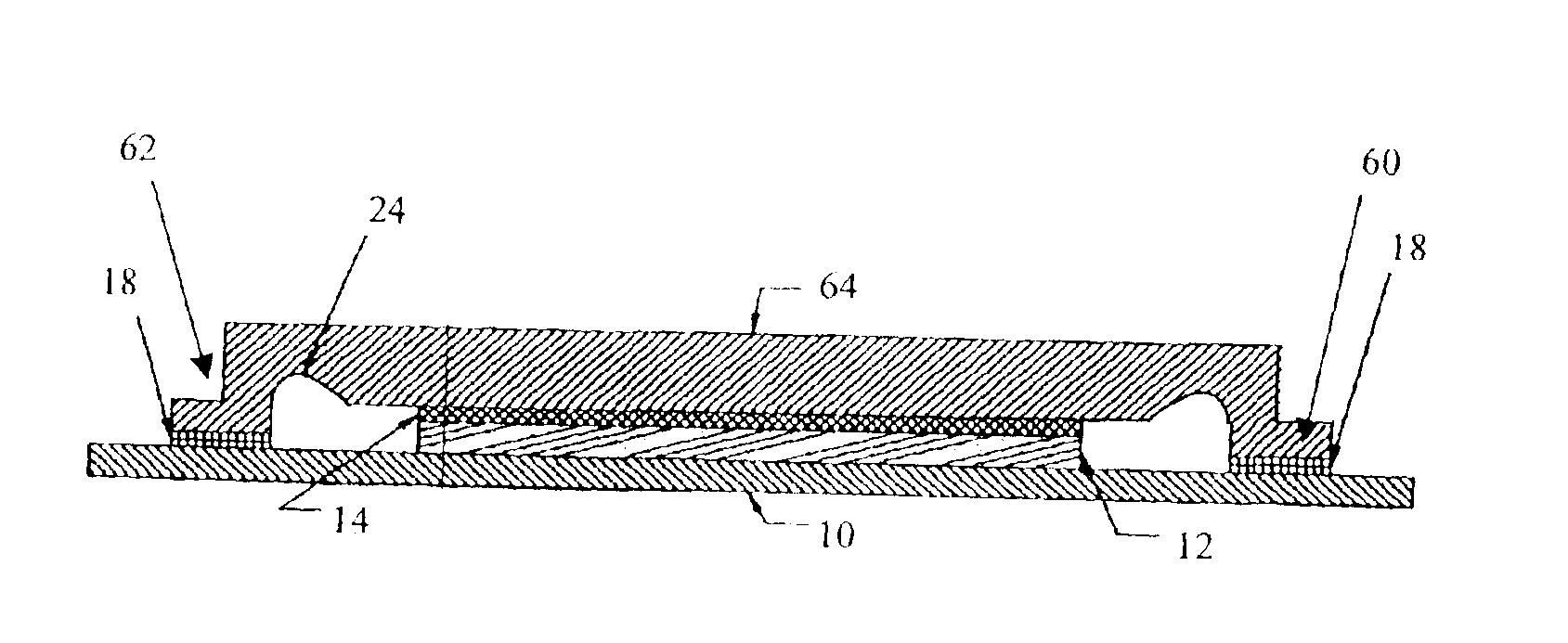
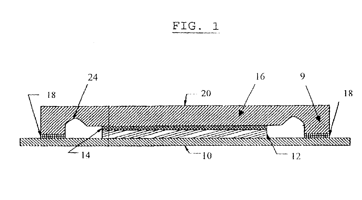
[0018]Disclosed is a heat spreader for electronic circuit components. Referring to FIG. 1, a semiconductor package is comprised of a substrate 10, a die 12, and an optional thermal interface material 14. A heat spreader lid 16 is bonded to substrate board 10 via bonding layer 18, and the lid 16 is thermally coupled to the die 12 via thermal interface material 14. Thermal interface material 14 is optional; the required thermal coupling can be accomplished either by direct physical contact of the lid with the underlying electronic component or via physical contact of the lid with a thermal interface material that transfers heat from the underlying electronic component. Many thermally conductive materials are suitable for use as thermal interface material. Typical thermal interface materials include silicone or polymer based adhesives doped with aluminum, silver, boron nitride, or aluminum nitride. Typical thermal interface materials also include lead, gold, or tin solder utilized in a...


PUM


Abstract

A heat spreader lid includes an outer periphery region having a lip for bonding to an underlying substrate board, a center region, and one or more strain isolation regions. The strain isolation regions are located between the center region and the outer periphery region and may comprise a number of slots cut partially or completely through the lid in a pattern surrounding or partially surrounding the center region. The strain isolation regions provide isolation of strain and relief of stress due to thermal expansion of the lid despite constraint at its periphery by the bonded lip, resulting in less thermally-induced warping of the center region, less thermally-induced stress on the bond between the lip and the substrate board, and/or less thermally-induced deflection of the substrate board. The reduced warping, stress, and/or deflection increases the reliability of the system by reducing the propensity for delamination or separation in the interface between the lid and the die, and/or by reducing the chance of structural failure in the bond between the lid and the substrate board.

Description

BACKGROUND OF THE INVENTION[0001]1. Field of the Invention[0002]The subject matter disclosed generally relates to the field of heat dissipation devices for electronics components.[0003]2. Background Information[0004]Many modern electrical devices, such as computers, include integrated circuits having many small circuit components that are fabricated on a fragile chip or “die.” Practical circuit components generate heat during operation. The complexity, compactness, and fragility of the circuitry on the die presents several challenges to designers of heat dissipation devices for the die. First, the heat dissipation device must facilitate adequate thermal egression to prevent an associated die from reaching an excessive temperature. Second, the heat dissipation device must be electrically isolated from the circuitry on the die so as not to interfere with the operation of the circuit. Third, the heat dissipation device must provide adequate rigidity to allow the fragile die to be handl...

Claims


Application Information

Patent Timeline
IPC IPC(8): H01L23/02H01L23/10
CPCH01L23/10H01L23/3675H01L2924/1616H01L2924/16152H01L2924/01079H05K5/03H05K7/20
Inventor BISH, JACKHANRAHAN, KEVINBRINK, DAMON
Owner HONEYWELL INT INC
Why Eureka
Try Eureka