Image sensing system and method of controlling operation of same

a technology of image data and image frame, which is applied in the field of image data sensing system, can solve the problems of reducing the number of image frames that can be recorded on the memory card, and affecting the image quality of the imag

Inactive Publication Date: 2005-06-14
FUJIFILM CORP
View PDF10 Cites 74 Cited by
  • Summary
  • Abstract
  • Description
  • Claims
  • Application Information

AI Technical Summary

Benefits of technology

[0007]Accordingly, an object of the present invention is to prevent the detrimental effects that accompany an increase in the number of pixels constituting a solid-state electronic image sensing device such as a CCD.

Problems solved by technology

Though an image obtained with a CCD having a large number of pixels has a high image quality, the amount of image data representing the image also is large.
As a consequence, there are detrimental effects such as a decline in the number of image frames that can be recorded on a memory card and a prolonged period of time for recording and for read-out.
However, if the designated area is dark, the entirety of the enlarged image also appears dark and is difficult to see.

Method used


Image

  • Image sensing system and method of controlling operation of same
  • Image sensing system and method of controlling operation of same
  • Image sensing system and method of controlling operation of same

Examples


first embodiment

[0034]the present invention will now be described with reference to the drawings.

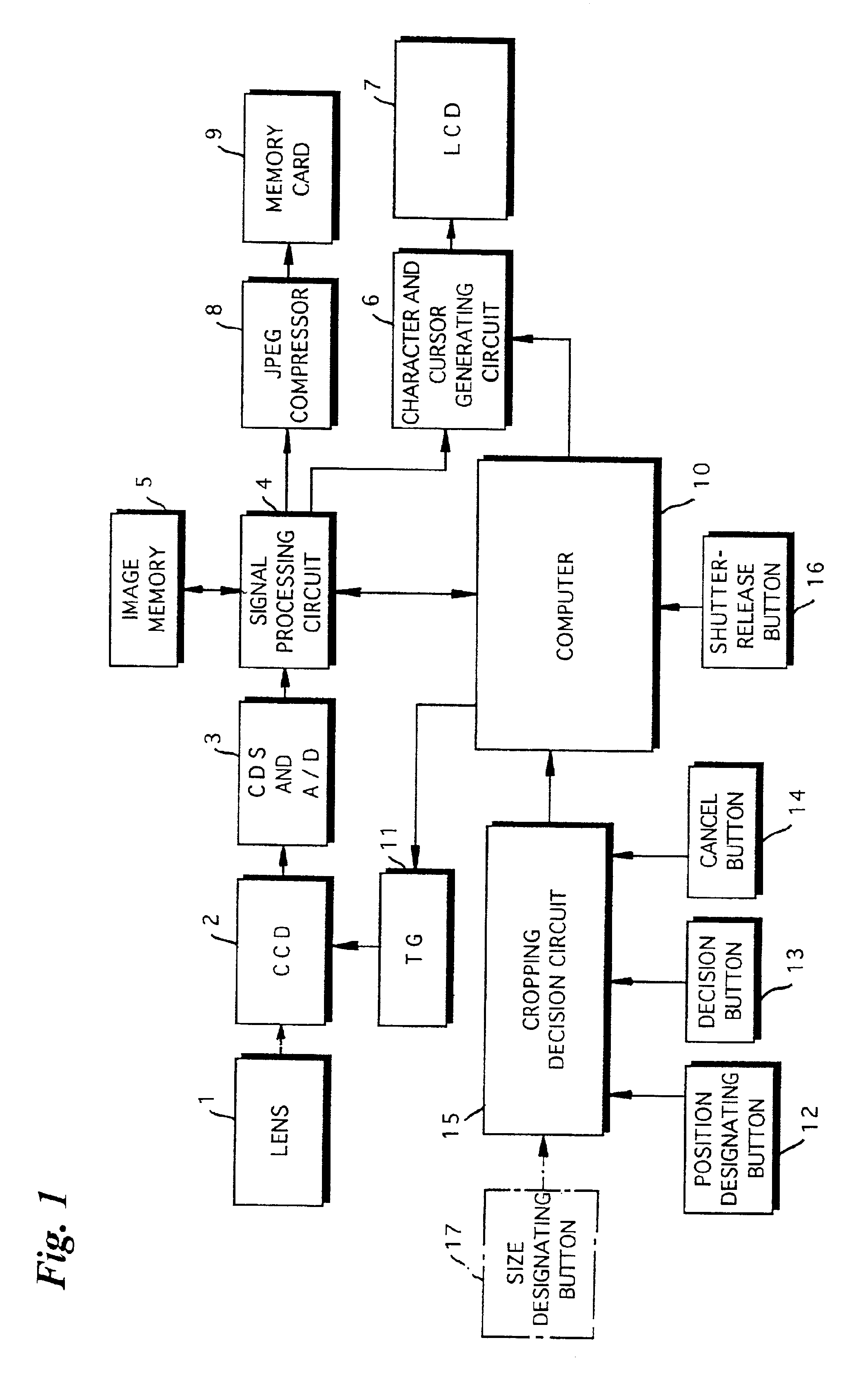
[0035]FIG. 1 is a block diagram illustrating the electrical construction of a digital still camera embodying the present invention.

[0036]The overall operation of the digital still camera is controlled by a computer 10 to which a shutter-release signal from a shutter-release button 16 is applied as an input.

[0037]The digital still camera according to this embodiment is capable of designating a desired area (referred to as a “cropping area”) in a full image capable of being sensed by a CCD 2. Image data representing an image within the designated cropping area is recorded on a memory card 9. To accomplish this, the digital still camera includes a position designating button 12 for designating the position of the cropping area, a decision button 13 for deciding the designated cropping area, and a cancel button 14. Signals indicative of operation of the buttons 12, 13 and 14 are input to a cropping decision...

second embodiment

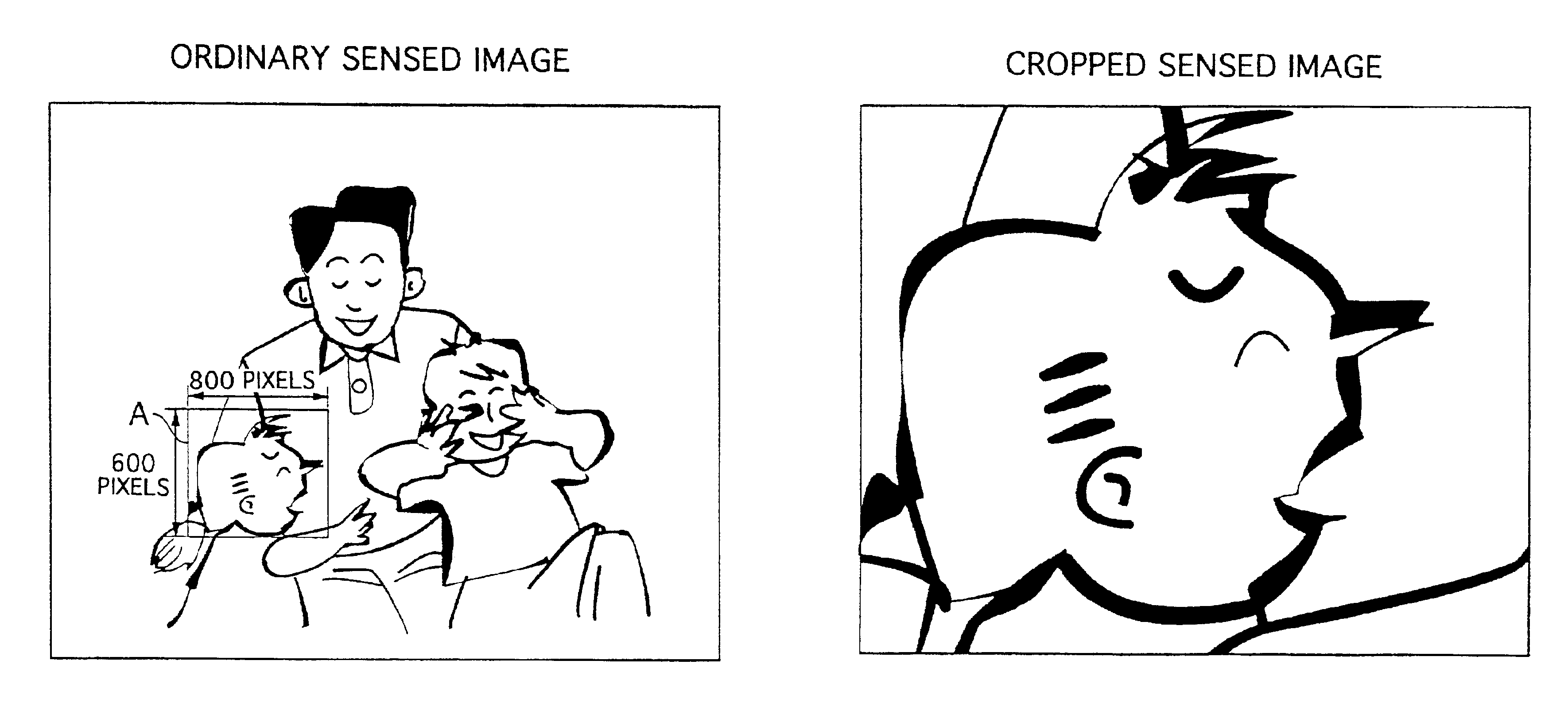
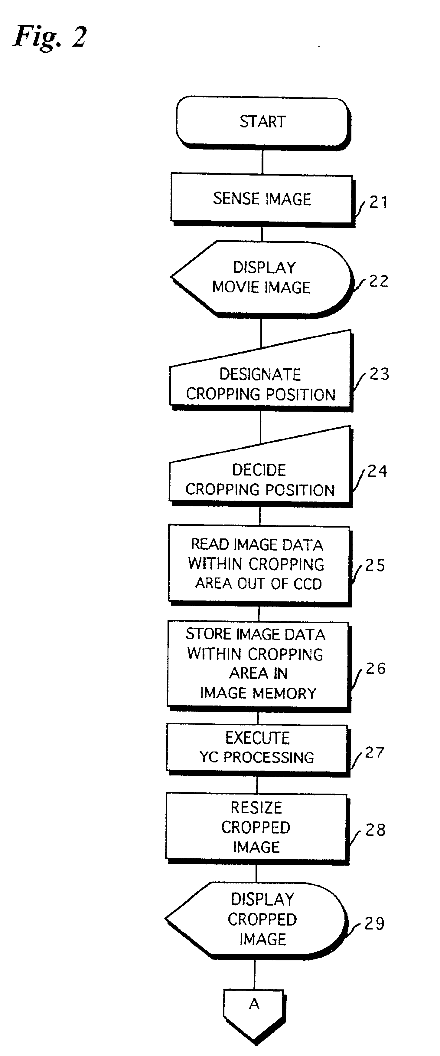
[0059]FIGS. 6 to 8 illustrate the present invention, in which FIG. 6 is a flowchart illustrating part of the processing executed by the digital still camera in this embodiment. Processing of steps in FIG. 6 identical with those shown in FIG. 2 are designated by like step numbers and need not be described again. FIGS. 7 and 8 illustrate examples of images displayed on the display screen of liquid crystal display device 7, in which FIG. 7 shows an example of an ordinary sensed image and FIG. 8 an example of a cropped sensed image.

[0060]In the above-described embodiment, the size of the cropping area is fixed. In this embodiment, however, the size of the cropping area can be changed. In this case, the digital still camera would be provided with a size designating button 17 for designating the size of the cropping area, as shown in FIG. 1.

[0061]The ordinary sensed image is displayed on the display screen of the liquid crystal display device 7 as described above (step 22). While observin...

third embodiment

[0064]FIGS. 9 to 11 illustrate the invention, in which FIG. 9 is a flowchart illustrating part of the processing executed by the digital still camera in this embodiment. FIGS. 10 and 11 illustrate examples of images displayed on the display screen of liquid crystal display device 7, in which FIG. 10 shows an example of an ordinary sensed image and FIG. 11 an example of a cropped sensed image. That part of the subject in FIGS. 10 and 11 is dark is indicated by hatching.

[0065]If the cropping area A is located in the dark portion of the subject, as shown in FIG. 10, the cropped image will be dark and difficult to see, as depicted in FIG. 11. This embodiment is such that when the cropping area A is in the dark portion of the subject, as mentioned above, the level of the luminance data is adjusted so as to obtain a suitable brightness and a cropped sensed image having this suitable brightness is displayed.

[0066]As set forth above, the cropping area A is designated and the cropped sensed ...


PUM


Abstract

When a subject is imaged for the purpose of deciding the angle of view, the full image that is capable of being sensed by a CCD is displayed on an LCD. The user designates the position of a cropping area in the image being displayed. Only image data representing the image within the border of the designated area is recorded on a memory card. Since the amount of image data to be recorded on the memory card is thus reduced, image data representing images of a greater number of frames can be recorded on the memory card.

Description

BACKGROUND OF THE INVENTION[0001]1. Field of the Invention[0002]This invention relates to an image sensing system for sensing the image of a subject and obtaining image data representing the image of the subject.[0003]2. Description of the Related Art[0004]The CCDs used in image sensing devices such as digital still cameras are being manufactured with ever greater numbers of pixels. This increase in the number of pixels used in CCDs has made it possible to obtain high-quality images.[0005]Though an image obtained with a CCD having a large number of pixels has a high image quality, the amount of image data representing the image also is large. As a consequence, there are detrimental effects such as a decline in the number of image frames that can be recorded on a memory card and a prolonged period of time for recording and for read-out.[0006]Digital cameras having a zoom function also are increasing in number. If a zoom area is designated in such a camera, the image within the design...

Claims


Application Information

Patent Timeline
Patent Type & Authority Patents(United States)
IPC IPC(8): H04N1/21H04N5/225H04N5/232G09G5/10G09G5/36H04N5/243H04N5/262H04N5/907H04N101/00
CPCH04N1/0044H04N1/2112H04N5/23293H04N5/2259H04N2201/212H04N2101/00H04N23/58H04N23/635
Inventor HIJISHIRI, HIDEAKISAITO, KENJI
Owner FUJIFILM CORP
Why Eureka
Try Eureka