Receiving apparatus for signal transmission system of orthogonal frequency division multiplexing type

a signal transmission system and receiving apparatus technology, applied in the field of receiving apparatuses for signal transmission systems of orthogonal frequency division multiplexing type, can solve problems such as noise in the reception of modulated signals, and achieve the effects of reducing noise, low error rate of code, and reducing noise levels

Inactive Publication Date: 2005-06-14
KOKUSA ELECTRIC CO LTD
View PDF15 Cites 43 Cited by
  • Summary
  • Abstract
  • Description
  • Claims
  • Application Information

AI Technical Summary

Benefits of technology

[0039]It is an object of the present invention to remove the above defects by providing a transmission system and a receiving apparatus of an OFDM scheme using the synchronous modulation method easy to handle and which can be easily used properly as a transmission apparatus suitable for the high-speed mobile radio transmission and a transmission apparatus suitable for transmission to the distance and can easily cope with sudden change of transmission conditions in a relay field.
[0047]However, since the pass bandwidth (250 Hz) of this time-axis direction interpolation circuit is narrower than that of the time-axis direction interpolation circuit having a wide pass bandwidth (2 kHz) used in the high-speed mobile radio transmission, noise can be reduced by about 10×log(2 kHz / 250 Hz)=9 dB.
[0048]With this operation, the transmission apparatus can be used as that which can reduce a noise level mixed into the reference signal vector and transmit information codes having low error rate of code and good quality to the distance.
[0049]As described above, according to the present invention, the receiving apparatus suitable for characteristics according to applications can be attained by operation of a switching circuit for switching a band limitation characteristic to a different one in accordance with transmission conditions. Accordingly, there can be obtained the receiving apparatus of the OFDM scheme using the synchronous modulation method without uselessness that various transmission apparatuses suitable for various applications must be provided and capable of coping with sudden change of conditions (transmission form) in the field easily to attain easy handling.

Problems solved by technology

On the other hand, a received modulated signal is affected by noise and other influences during a transmission process and distorted.

Method used


Image

  • Receiving apparatus for signal transmission system of orthogonal frequency division multiplexing type
  • Receiving apparatus for signal transmission system of orthogonal frequency division multiplexing type
  • Receiving apparatus for signal transmission system of orthogonal frequency division multiplexing type

Examples


first embodiment

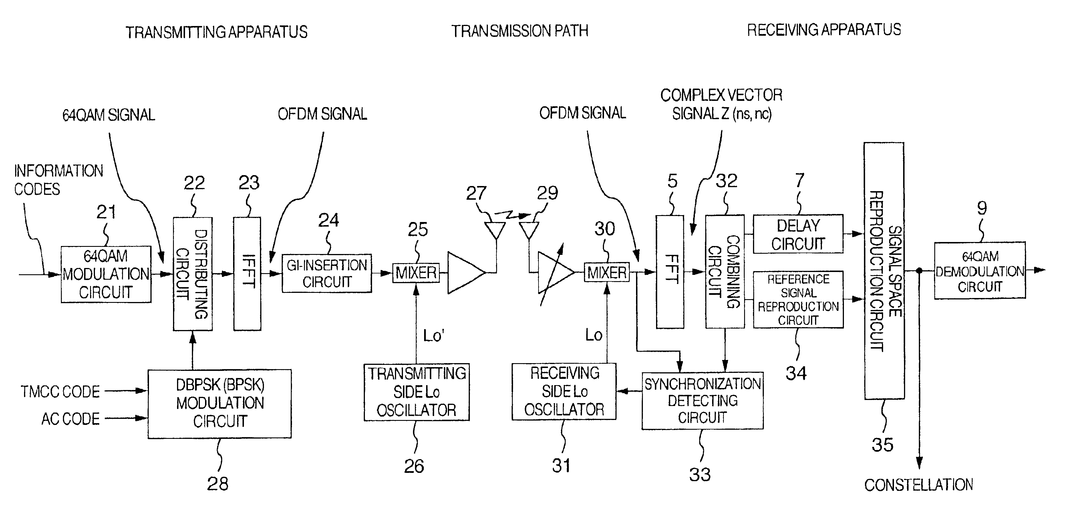
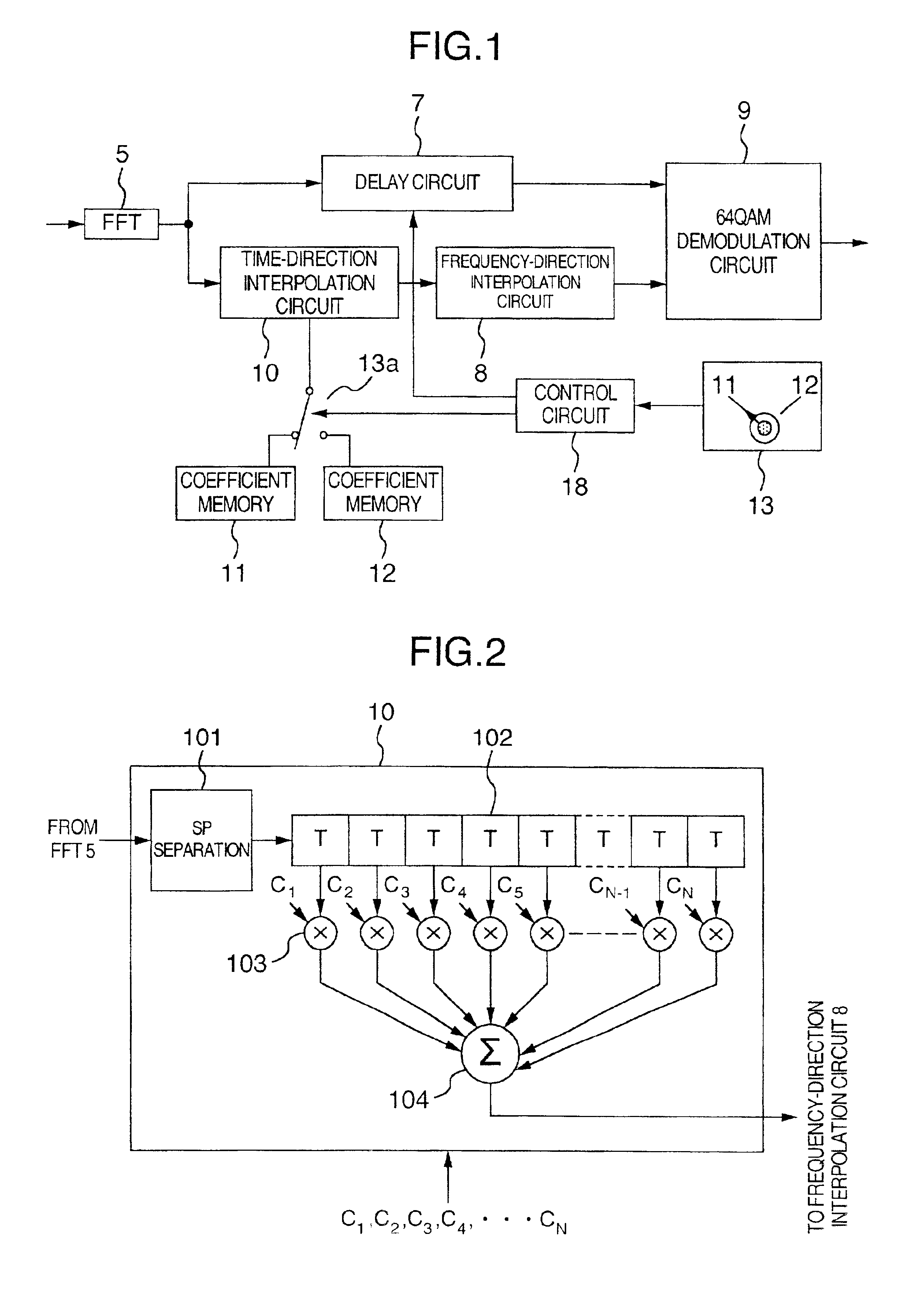
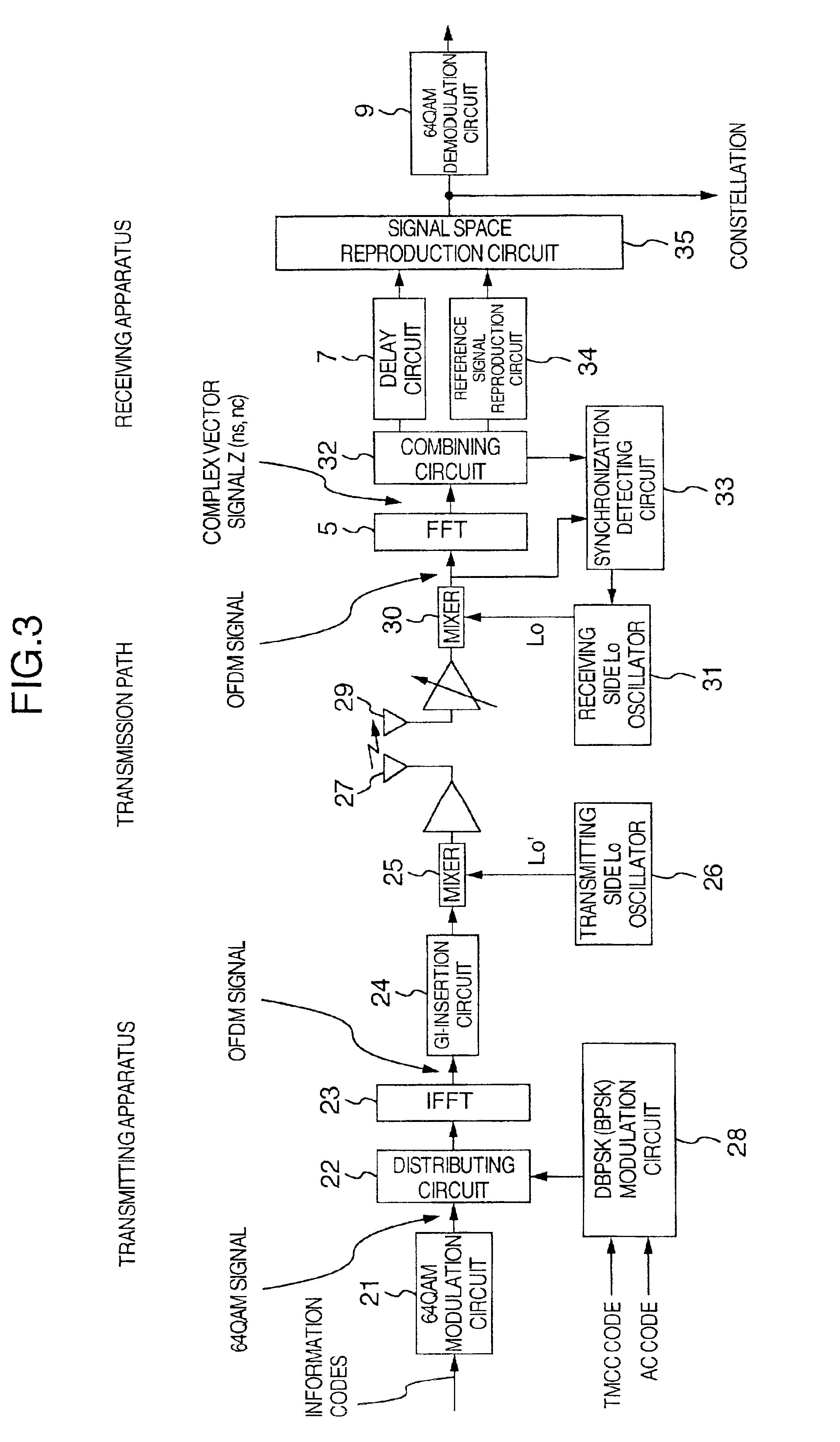
[0065]FIG. 1 is a schematic diagram illustrating a first embodiment according to the present invention and particularly FIG. 1 illustrates a circuit portion for reproducing a reference signal vector of a receiving apparatus of the OFDM scheme. The first point thereof different from the conventional circuit of FIG. 11 is that coefficient memories for storing coefficient values of an LPF used in a time-direction interpolation circuit 10 is disposed outside of the interpolation circuit 10. The second point different from the conventional circuit is that two or more coefficient memories are provided and switched by a switch 13a controlled by a control circuit 18 by means of an operation unit 13 so that an optimum coefficient value can be used in accordance with transmission conditions. The third point different from the conventional circuit is that a delay time of a delay circuit 7 is also switched simultaneously when the plurality of coefficient memories are switched.

[0066]The blocks o...

second embodiment

[0083]the present invention is now described.

[0084]The second embodiment is different from the first embodiment in that the second embodiment uses a carrier structure in which pilot signals (CP) are inserted continuously in the time direction as shown in FIG. 4, whereas in the first embodiment it is premised that the pilot signals SP are inserted at regular intervals in the time direction as shown in FIG. 10. In FIG. 4, the mark indicating the positions where the pilot signals are inserted is changed to CP (Continual Pilot) for emphasizing continuous insertion in order to clear the difference from the carrier structure of FIG. 8 where the pilot signals are inserted sporadically.

[0085]In the case of the carrier structure shown in FIG. 4, the pilot signals CP are continuously inserted into carriers having a certain frequency in the time direction.

[0086]Accordingly, in the interpolation in the frequency direction, the pilot signals CP can be used as they are and it is not necessary to ...


PUM


Abstract

A signal transmission system of an OFDM using a plurality of carriers to transmit signal comprises a transmitting apparatus and a receiving apparatus. The receiving apparatus comprises an input unit for applying the OFDM signal from the transmitting apparatus; a fast Fourier transforming unit for separating the OFDM signal from the input unit into base-band signals including pilot signals; an interpolation unit for interpolating the pilot signals in a time-axis direction and a frequency-axis direction to calculate reference signal vectors of the carriers in which the pilot signals are not included; a demodulation unit for decoding to be produced as information codes; a delay a unit for adjusting a delay time of said base-band signals passing the delay unit; and a control unit coupled with the interpolation unit, for changing frequency band characteristics of the interpolation unit.

Description

BACKGROUND OF THE INVENTION[0001]The present invention relates to a signal transmission system and a receiving apparatus each using an orthogonal frequency division multiplexing (hereinafter abbreviated as OFDM) scheme for transmitting information codes by means of a plurality of carriers orthogonal to one another and more particularly to a receiving apparatus for the signal transmission apparatus of the OFDM scheme in which the plurality of carries of the OFDM scheme are modulated in accordance with a modulation scheme accommodated to the synchronization detection (hereinafter referred to as synchronous modulation scheme).[0002]In recent years, in the field of radio devices, the OFDM scheme is in the limelight as a modulation scheme immune to multipath fading. A large number of applied studies on the OFDM are now in progress in the fields of next-generation television broadcasting, FPU (Field Pick-up Unit), radio LAN and so on in many countries including European countries and Japa...

Claims


Application Information

Patent Timeline
Patent Type & Authority Patents(United States)
IPC IPC(8): H04L27/26H04N5/40H04J11/00H04L7/00
CPCH04L27/2647
Inventor AKIYAMA, TOSHIYUKI
Owner KOKUSA ELECTRIC CO LTD
Why Eureka
Try Eureka