Variable turbocharger

a variable geometry, turbocharger technology, applied in the direction of liquid fuel engines, machines/engines, forging/pressing/hammering apparatus, etc., can solve the problems of difficult to maintain the effective sealing condition of the slit, practicably impossible for the charging compressor to operate effectively, etc., to achieve the effect of reducing the dimensional size of the variable geometry turbocharger, improving the sealing effect of the housing, and structurally simplifying

Inactive Publication Date: 2005-06-21
KOMATSU LTD
View PDF10 Cites 22 Cited by
  • Summary
  • Abstract
  • Description
  • Claims
  • Application Information

AI Technical Summary

Benefits of technology

[0028]With this arrangement, the rotational driving force coming from an external motor or the like is transmitted to the swing drive shaft outside the housing of the

Problems solved by technology

Since such a turbocharger utilizes exhaust gas of an engine, the flow rate of exhaust gas is reduced and hence the exhaust turbine revolves at a low rpm in a low rpm range of the engine so that it is practically

Method used


Image

  • Variable turbocharger
  • Variable turbocharger
  • Variable turbocharger

Examples


Embodiment Construction

[0035]Now, the present invention will be described by referring to the accompanying drawings according to an embodiment of the present invention.

[0036]Firstly, the configuration of the embodiment will be described below.

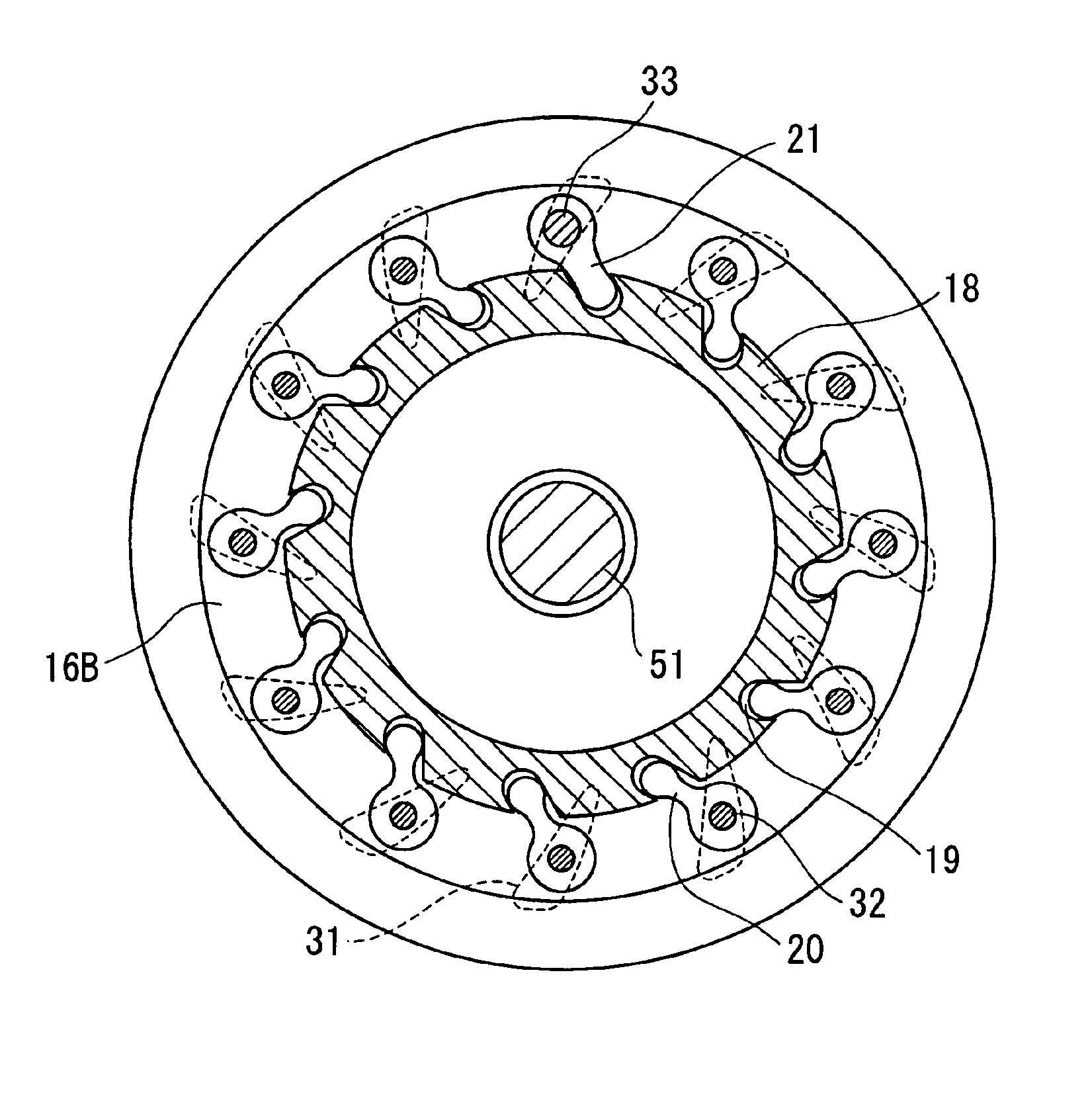
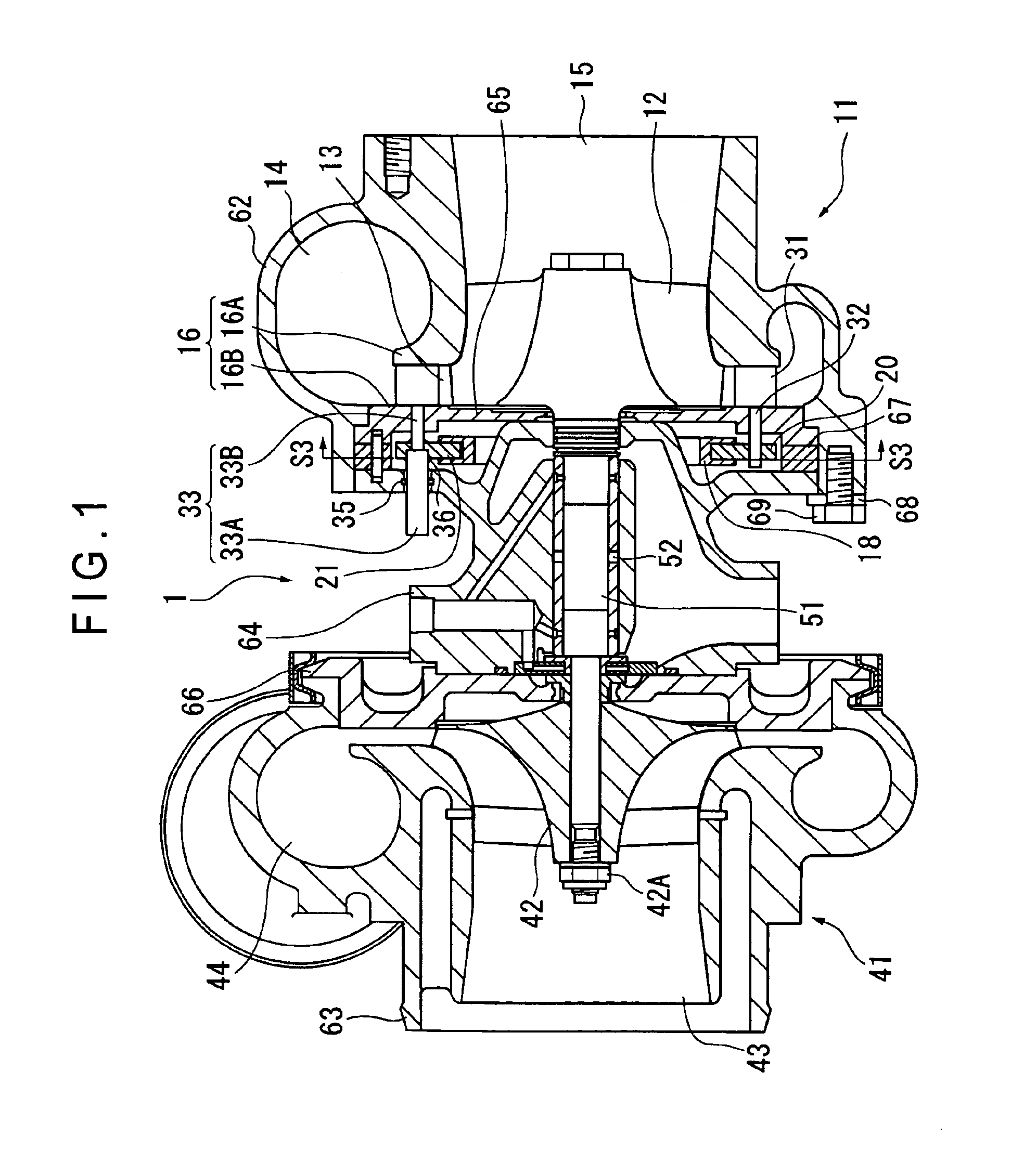
[0037]FIG. 1 is a cross sectional view of the embodiment, showing the overall configuration thereof.

[0038]Referring to FIG. 1, a variable geometry turbocharger 1 includes an exhaust turbine 11 and a charging compressor 41.

[0039]The exhaust turbine 11 is arranged midway of the exhaust flow path of an engine (not shown) and provided with a turbine housing 62 that guides the inflow and the outflow of exhaust gas and an exhaust turbine wheel 12 contained in the turbine housing 62.

[0040]The turbine housing 62 is provided as integral parts thereof with an exhaust inflow section 14 arranged at the outer peripheral side thereof and having a cross section that diminishes toward the inflow front end and an exhaust outflow section 15 arranged at the center and having a substant...


PUM

PropertyMeasurementUnit
Angleaaaaaaaaaa
Durabilityaaaaaaaaaa

Abstract

One of the swing shafts 32 of the nozzle vanes 31 is selected so as to operate as swing drive shaft 33 that projects to the outside. As the swing drive shaft 33 is driven to revolve, all the nozzle vanes 31 are driven to turn by a same angle by way of the driving lever 21 and the coupling ring 18 linked to it. Therefore, it is only the swing drive shaft 33 that projects to the outside, the projecting part can be sealed in a simple and reliable manner to improve the sealing effect and the durability of the variable geometry turbocharger. Additionally, since the rotary motion of the swing drive shaft 33 is directly used to driven the nozzle vanes 31 to swing, the mechanism for transmitting the driving force is simplified.

Description

[0001]This application is a U.S. National Phase Application under 35 USC 371 of International Application PCT / JP02 / 12501 filed Nov. 29, 2002.TECHNICAL FIELD[0002]This invention relates to a turbocharger. More particularly, the present invention relates to a variable geometry turbocharger provided with nozzle vanes to regulate the exhaust flow rate of an exhaust turbine.BACKGROUND ART[0003]Turbochargers adapted to driving an exhaust turbine, utilizing exhaust energy of an engine, to by turn drive a charging compressor are known as a method for compressing air and causing the engine to take in compressed air. Since such a turbocharger utilizes exhaust gas of an engine, the flow rate of exhaust gas is reduced and hence the exhaust turbine revolves at a low rpm in a low rpm range of the engine so that it is practically impossible for the charging compressor to operate effectively. A method of making the nozzle area of the turbocharger variable is known to improve its performance. Such a...

Claims


Application Information

Patent Timeline
IPC IPC(8): F01D17/16F01D17/00F02B37/24F02C6/12F02B37/12F02C6/00
CPCF01D17/165F02B37/24F02C6/12Y10T29/49323Y02T10/144F05D2220/40Y02T10/12F02B37/12
Inventor NISHIYAMA, TOSHIHIKOSUGITO, HIROSHIIINO, TAKAHISA
Owner KOMATSU LTD
Why Eureka
Try Eureka