
Multiple operating mode engine and method of operation

a multi-mode, engine technology, applied in the direction of engine starters, electric control, instruments, etc., can solve the problems of increasing the challenge to contemporary designers, difficulty in overstating the importance of the engine or the engineering effort expended in seeking its perfection, and increasing the cost. , to achieve the effect of effective and efficient transfer of operation

Inactive Publication Date: 2005-06-21
CUMMINS INC
View PDF38 Cites 88 Cited by
  • Summary
  • Abstract
  • Description
  • Claims
  • Application Information

AI Technical Summary

Benefits of technology

[0013]A general object of the subject invention is to overcome the deficiencies of the prior art by providing a practical multi-mode engine and a method for operating the engine in various modes and effectively and efficiently transferring operation between the various modes.
[0015]Yet another object of the present invention is to provide a multi-mode internal combustion engine capable of transitioning between a diesel mode while maximizing natural gas usage and minimizing diesel flow rates.

Problems solved by technology

It would be difficult to overstate its importance or the engineering effort expended in seeking its perfection.
Emissions abatement or improved reliability can also be achieved with an increase in cost.
The challenge to contemporary designers has been significantly increased by the need to respond to governmentally mandated emissions abatement standards while maintaining or improving fuel efficiency.
In view of the mature nature of engine design, it is extremely difficult to extract both improved engine performance and emissions abatement from further innovations of the basic engine designs commercially available today.
Yet the need for such innovations has never been greater in view of the series of escalating emissions standards mandated for the future by the United States government and other countries.
As a result, there are important differences in the advantages and disadvantages of diesel and spark-ignited engines.
Typical diesel engines, however, cannot achieve the very low NOx and particulate emissions levels which are possible with premixed charge spark ignited engines.
Due to the mixing controlled nature of diesel combustion a large fraction of the fuel exists at a very fuel rich equivalence ratio which is known to lead to particulate emissions.
Premixed charge spark ignited engines, on the other hand, have nearly homogeneous air fuel mixtures which tend to be either lean or close to stoichiometric, resulting in very low particulate emissions.
The high temperatures, in turn, cause high NOx emissions.
Lean burn premixed charge spark ignited engines, on the other hand, burn their fuel at much leaner equivalence ratios which results in significantly lower temperatures leading to much lower NOx emissions.
Stoichiometric premixed charge spark ignited engines, on the other hand, have high NOx emissions due to the high flame temperatures resulting from stoichiometric combustion.
Although PCCI combustion may result in improved fuel economy and substantially reduced emissions, it is difficult for an engine to operate in a PCCI mode over a wide range of operating conditions, ranging from cold start-up to various levels of engine load.
It was found that at very light loads, PCCI was not successful because charge temperatures were too low.
At very high loads, PCCI was not successful because the residual gas quantity was too low.
SAE papers 920512 and 972874 are noted for disclosing experimental results comparing PCCI combustion to spark-ignition combustion, but fail to specifically teach the manner in which transitions between modes of operation could be most effectively achieved.

Method used


Image

  • Multiple operating mode engine and method of operation
  • Multiple operating mode engine and method of operation
  • Multiple operating mode engine and method of operation

Examples


Embodiment Construction

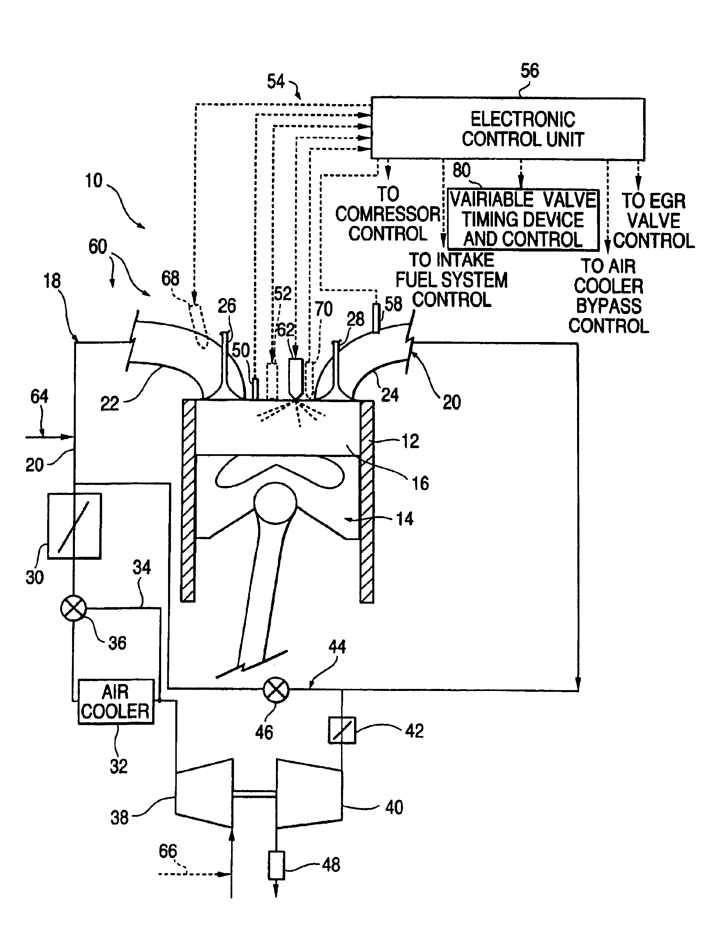
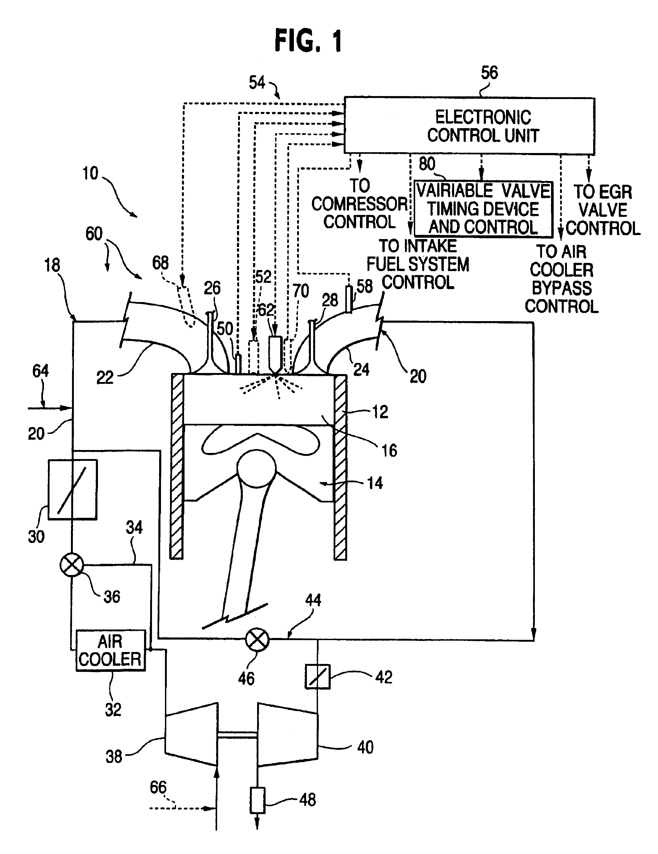
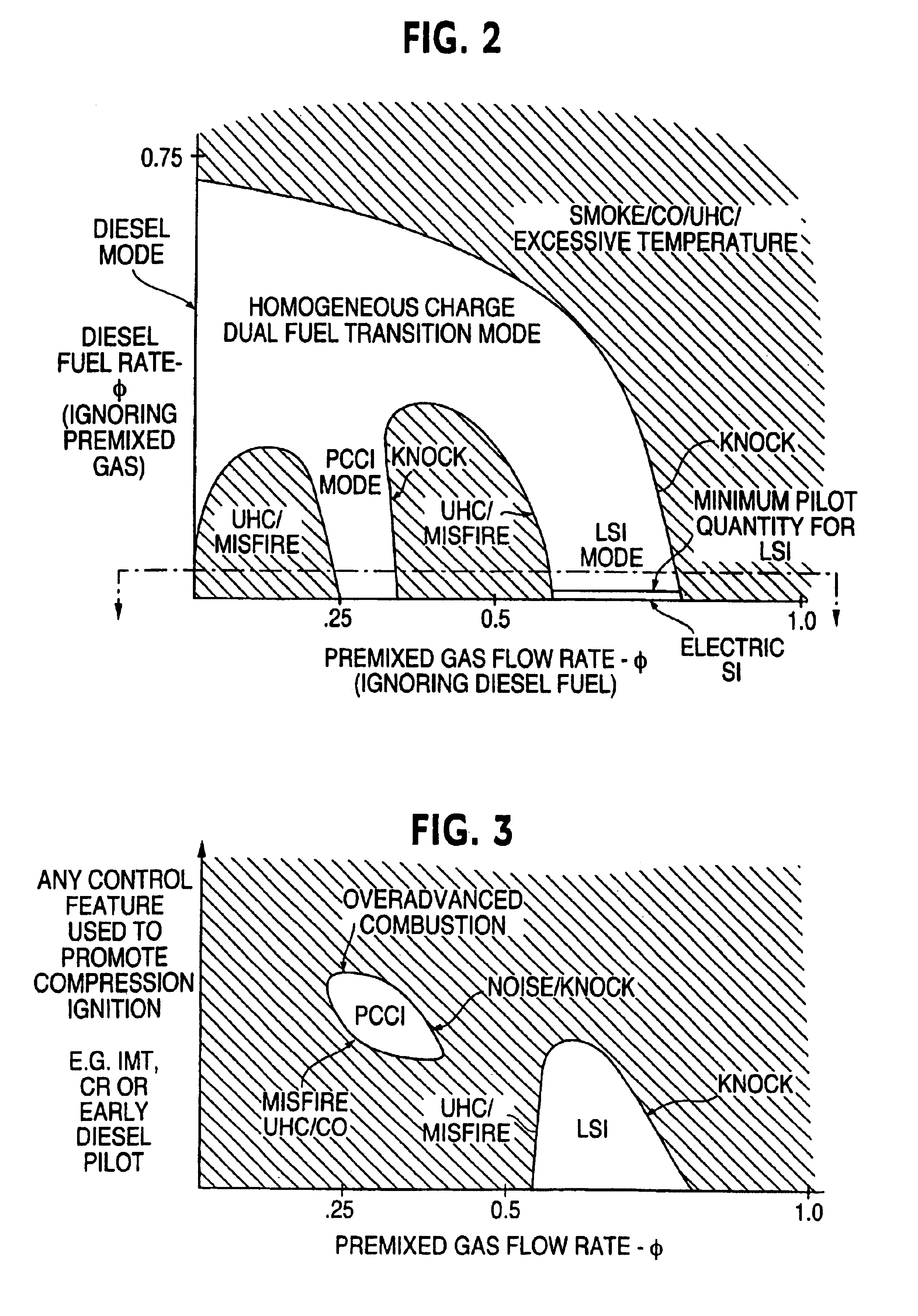
[0036]The present invention as described in further detail hereinbelow is directed to an improved internal combustion engine capable of operating in and transitioning or transferring between different operating modes to improve fuel efficiency and reduce exhaust emissions while increasing startability and load handling across a range of engine operating conditions. Specifically, the multi-mode engine of the present invention, as generally shown at 10 in FIG. 1, may be operated in a premixed charge compression ignition (PCCI) mode, a diesel mode, a spark ignition (SI) mode and a homogeneous charge dual fuel transition (HCDFT) mode. A PCCI mode of operation refers to a combustion event wherein: 1) the majority of fuel is sufficiently premixed with air to form a combustible mixture throughout the charge at the time of ignition; and 2) ignition (start of combustion) is initiated by compression ignition, which includes homogeneous charge compression ignition (HCCI) engines. It should be ...


PUM


Abstract

A multi-mode internal combustion engine and method of operating the engine is provided which is capable of operating in a variety of modes based on engine operating conditions to enhance fuel efficiency and reduce emissions. The multi-mode engine include a fuel delivery system and control system for permitting the engine to operate in a diesel mode, a homogeneous charge dual fuel transition mode, a spark ignition or liquid spark ignition mode and / or a premixed charge compression ignition mode. The control system and method permits the engine operation to transfer between the various modes in an effective and efficient manner by controlling one or more fuel delivery devices or other engine components so as to move along a continuous transfer path while maintaining engine torque at a substantially constant level.

Description

[0001]This application is a divisional of application Ser. No. 10 / 387,579, filed Mar. 14, 2003 now U.S. Pat. No. 6,884,849, which is a divisional of application Ser. No. 09 / 850,189, filed May 8, 2001, now U.S. Pat. No. 6,561,157, which is a non-provisional of provisional application Serial No. 60 / 202,850, filed May 8, 2000.TECHNICAL FIELD[0002]This invention relates generally to an internal combustion engine capable of operating in, and transitioning between, different operating modes including a premixed charge compression ignition mode, a diesel mode and / or spark ignition mode.BACKGROUND OF THE INVENTION[0003]For well over 75 years the internal combustion engine has been mankind's primary source of motive power. It would be difficult to overstate its importance or the engineering effort expended in seeking its perfection. So mature and well understood is the art of internal combustion engine design that most so called “new” engine designs are merely designs made up of choices amon...

Claims


Application Information

Patent Timeline
IPC IPC(8): F02D15/04F02B23/06F02D19/10F02D35/02F02D41/00F02D19/00F02D19/06F02B23/02F02B1/12F02D13/02F02D41/40F02D9/04F02B37/18F02B37/22F02D9/00F02B1/00F02B17/00F02D41/30F02M69/04F02D15/00F02B69/00F02B37/12F02M43/00F02M45/02F02M45/00F01N3/28F02B3/00F02B1/04F02B75/12F02B3/06F02B75/00F02M25/07F02B11/00F02D9/02F02D19/02F02D19/08F02D21/08F02D23/02F02D41/02F02D41/04F02D41/06F02D41/34F02D41/38F02D43/00F02D45/00F02M21/02F02M21/04F02M63/00F02N11/04
CPCF02B1/12F02B17/005F02B23/0672F02B37/18F02B37/22F02B69/00F02D9/04F02D13/0203F02D13/0215F02D13/0234F02D13/0269F02D15/04F02D19/0631F02D19/0647F02D19/081F02D19/105F02D35/02F02D35/023F02D35/025F02D35/028F02D41/0025F02D41/0027F02D41/3035F02D41/3064F02D41/3094F02D41/40F02D41/401F02D41/402F02D41/403F02D41/405F02M43/00F02M45/02F02M69/044F02M69/045F02M69/046F02N11/04F02D19/061F02D19/0689F02D19/0692F02B1/04F01N3/28Y02T10/36F02B3/06F02B29/0406F02B29/0418F02B2075/125F02D2041/389F02D2250/18F02M25/0707F02M25/0713F02M25/0752Y02T10/125Y02T10/128Y02T10/44Y02T10/123Y02T10/144Y02T10/142Y02T10/42F02D35/022F02M26/05F02M26/10F02M26/01Y02T10/12Y02T10/40Y02T10/30
Inventor ZUR LOYE, AXEL O.BRACKNEY, LARRY J.CHENANDA, CARIAPPA M.HURST, ROBERT M.PETERS, LESTER L.PIERZ, PATRICK M.WRIGHT, JOHN F.
Owner CUMMINS INC
Learn More