Method and installation for producing a metal strip

a technology of metal strips and production methods, applied in the direction of manufacturing tools, flexible work arrangements, tensioning/braking arrangements, etc., can solve the problems of cracks and damage to the strip surface, affecting the quality of the product produced, and rising the risk of cracking in the immediate vicinity of the casting gap, so as to achieve the highest possible strip quality

Inactive Publication Date: 2005-06-21
VOEST ALPINE AG
View PDF15 Cites 5 Cited by
  • Summary
  • Abstract
  • Description
  • Claims
  • Application Information

AI Technical Summary

Benefits of technology

[0008]The object of the invention is, therefore, to avoid these disadvantages and to propose a method and a plant of the type described in the introduction, in which the metal strip formed in the casting plant runs, largely free of load and without reactions from following devices, through the first cooling and structure-forming phase. The object of the invention is, further, to keep the dead-weight load on the metal strip as constant as possible in this phase after the formation of the metal strip and nevertheless to make it possible to vary the transport speed in following devices. Further, an optimization of the production process in terms of the uniformly highest possible strip quality is to be achieved.

Problems solved by technology

A substantial disadvantage of this plant arrangement is that the casting speed in the two-roll casting device and the rolling speed in the rolling stand have to be constantly co-ordinated with one another and even minor speed deviations in one of the plant components give rise to reactions on other plant components which are detrimental to the quality of the product produced.
As a result of the brief intermediate storage, the two-roll casting device is separated functionally from the winding plant to the extent such that jolt-like movements in the metal strip which emanate from the strip winder do not react into the region of the casting plant and the high-temperature zone of the metal strip and lead to damage there.
Due to the long metal-strip loop which fluctuates in length and which extends, hanging down freely under its own weight, directly from the casting gap and, by being deflected, undergoes an undefined pendulum movement, sharply fluctuating tensile stresses for the metal strip arise, which lead to the formation of cracks and to damage to the strip surface.
Where relatively large strip thicknesses are concerned, the risk of cracking rises in the immediate vicinity of the casting gap owing to the increasing dead weight.
Even when the metal strip forms a strip loop in a loop pit only after being supported by some supporting rollers, adverse reactions of the loop movement on the stress conditions in the metal strip in the region near the casting gap occur.
The strip sag of variable length in the loop pit causes different strip-tension conditions upon entry into the hot-rolling mill, with the result that adherence to a uniform strip quality is not ensured.
In addition, the strip runs out of true laterally in the rolling stand.

Method used


Image

  • Method and installation for producing a metal strip
  • Method and installation for producing a metal strip
  • Method and installation for producing a metal strip

Examples


Embodiment Construction

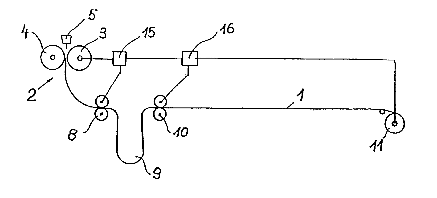
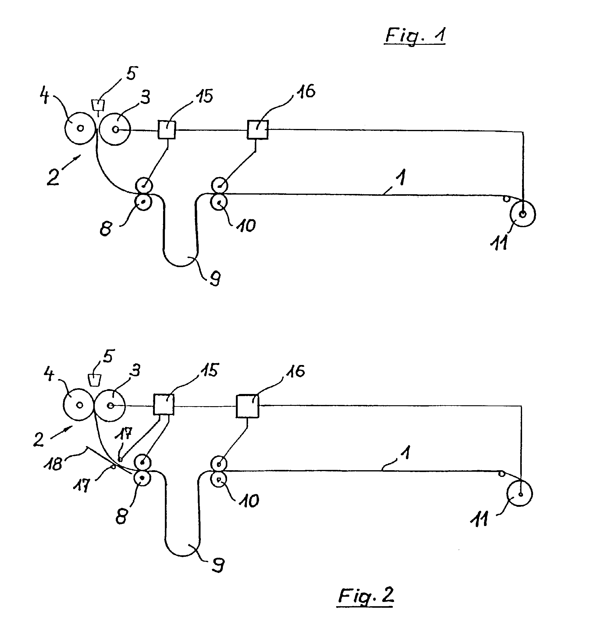
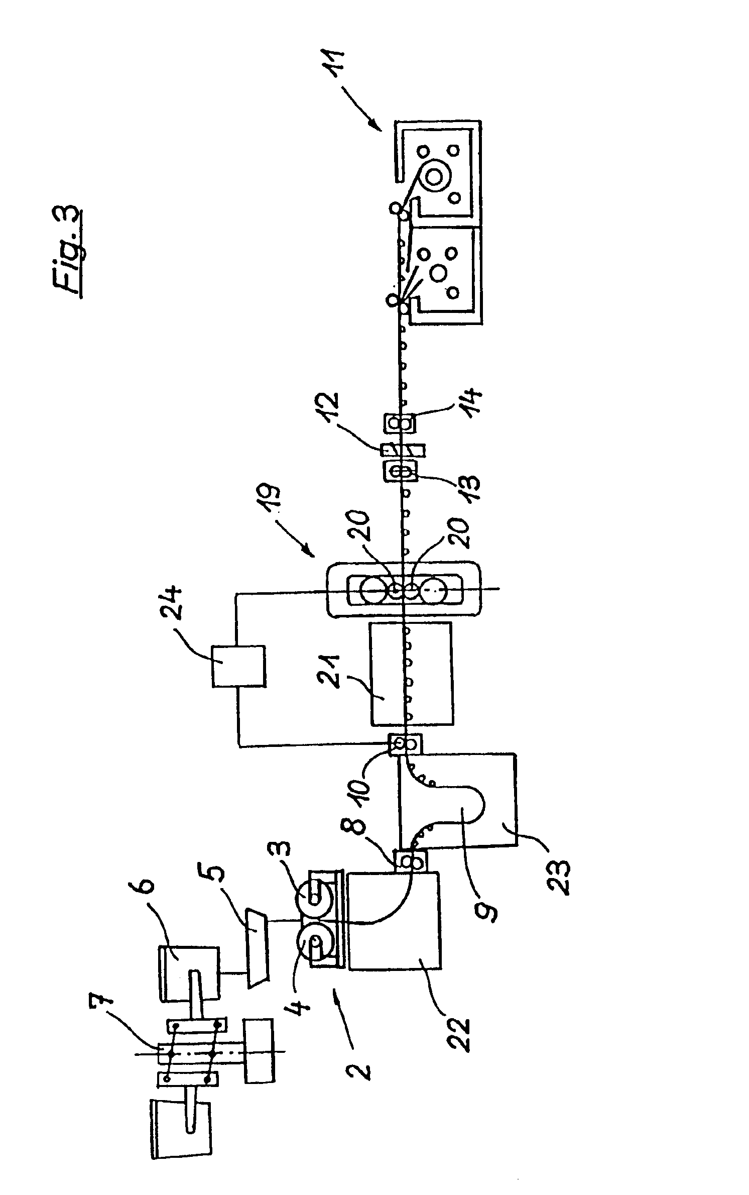
[0023]According to an advantageous refinement of the invention, the position of the metal strip in the region of deflection from the vertical direction into the horizontal direction, preferably the resting point of the metal strip on a deflecting support device, is detected by measurement by means of a strip location device and a strip transport speed in the first driving-roller stand and / or the casting speeds in the casting gap are regulated as a function of this. By virtue of a deflecting support device which is designed as an arcuate guide scaffold and is mounted pivotably in the plant supporting framework and extends only over a subsection of the path from the first driving-roller stand to the two-roll casting device, regulatability within a narrow, but sufficient range is maintained.

[0024]In so far as no further treatment steps on the metal strip which influence the strip speed are provided, the winding-up of the metal strip under tension can advantageously be regulated as a fu...


PUM

PropertyMeasurementUnit
thicknessaaaaaaaaaa
thicknessaaaaaaaaaa
thicknessaaaaaaaaaa

Abstract

The invention relates to a method and to an installation for producing a metal strip. The aim of the invention is to make sure that the metal strip formed in the casting installation passes through the first cooling and grain texturing phase substantially without being subjected to stress and without effects on the subsequent installations. To this end, the molten bath is fed to a two-roll casting device and a cast metal strip is formed in the casting gap between two casting rolls whose rotational axes lie in a horizontal plane (two-roll casting method), the thickness of the cast strip ranging between 1.0 to 20 mm, preferably between 1.5 to 12 mm. The cast metal strip that freely emerges downwards from the two-roll casting installation is directly deflected from the vertical casting direction to a substantially horizontal transport direction. The metal strip is taken up and conveyed in a controlled manner by means of a first drive roll stand that operates at a first transport speed. The metal strip is then stored for a short time in a strip accumulator, and is then taken up and conveyed by means of a second drive roll stand that operates at a second transport speed. In a final step, the metal strip is coiled up to a bundle under pretension.

Description

CROSS REFERENCE TO RELATED APPLICATIONS[0001]This is a continuation of International Application No. PCT / EP01 / 05394, filed May 11, 2001, published in the German language at A400685WO, and which claims priority from Austrian application No. A 982 / 2000, filed Jun. 5, 2000.BACKGROUND OF THE INVENTION[0002]1. Field of the Invention[0003]The invention relates to a method and a plant for the production of a metal strip, preferably a steel strip, in particular consisting of stainless steel and carbon steel, with a casting thickness of 1.0 mm to max. 20 mm, preferably 1.5 mm to max. 12 mm, and with excellent surface quality, using the two-roll casting method and further treatment stages.[0004]2. Description of the Related Art[0005]EP-A 776 984 already discloses a plant of this type for the production of a metal strip according to the two-roll casting method. This two-roll casting device is followed by a hot-rolling stand, by means of which the cast strip is rolled to form an intermediate pr...

Claims


Application Information

Patent Timeline
Patent Type & Authority Patents(United States)
IPC IPC(8): B22D11/06B21B1/46B21B27/10B21B1/00B21B39/08B21B41/08B21B45/00B21C47/02B21C49/00B22D11/12B22D11/20
CPCB21B1/463B22D11/0622B21B41/08B22D11/06
Inventor HOHENBICHLER, GERALDPUHRINGER, HEINRICHFINSTERMANN, GERHARDFUHRMANN, ERNEST
Owner VOEST ALPINE AG
Why Eureka
Try Eureka