Diesel injection nozzle

a diesel engine and nozzle technology, applied in the direction of fuel injecting pumps, functional valve types, machines/engines, etc., can solve the problems of degeneration of fuel penetration and fuel dispersion in the engine cylinder, correspondingly degrade emissions performance, and not doing anything to reduce the volume of the sac, so as to improve emissions performance and improve emissions performance. performance

Inactive Publication Date: 2005-06-21
BUESCHER DEV
View PDF7 Cites 5 Cited by
  • Summary
  • Abstract
  • Description
  • Claims
  • Application Information

AI Technical Summary

Benefits of technology

[0011]The invention realizes these results by exploiting the geometrical fact that for solids generated by revolution of a polygon of given area (sweep area) around an axis in the same plane, relatively small percentage reductions of sweep area caused by trimming the radially outer side of the sweep area result in significantly larger percentage reductions of swept volume. This means that, in an injection nozzle, a relatively small percentage reduction in the sac's cross-section at its radially outermost parts results in a significantly greater percentage reduction in sac volume.

Problems solved by technology

Lower seat / orifice ratios are associated with higher pressure drops through the body seat and lower injection pressures at the nozzle orifices, with a resultant degeneration of fuel penetration and fuel dispersion in the engine cylinder.
However, in certain high rated engines, when the orifice area required for the engine power rating gets to be too large for the nozzle size accommodated in the engine cylinder head, the seat / orifice ratio is considered not excessively restrictive down to 1.5, and in extreme cases is compromised down to 1.35.
Increasing valve lift would of course increase minimum flow area at full lift, but there are well-known constraints on increasing lift, such as body seat impact damage and coordination of valve seating and engine stroke phases in high-rated engines.
It was recognized however, that such a modification of the ALCO nozzle would have a major disadvantage in that sac volume would be substantially increased by enlarging the sac diameter along the length of the sac, thereby tending to correspondingly degrade emissions performance.
While this modification has increased seat / orifice ratio while somewhat minimizing increase in sac volume, it has done nothing to reduce sac volume and improve emissions performance in that way.
Moreover, even if sac volume had been reduced, as by foreshortening the sac, the configuration of the notch was such as to limit to some degree the effectiveness of such foreshortening in reducing emissions.

Method used


Image

  • Diesel injection nozzle
  • Diesel injection nozzle
  • Diesel injection nozzle

Examples


Embodiment Construction

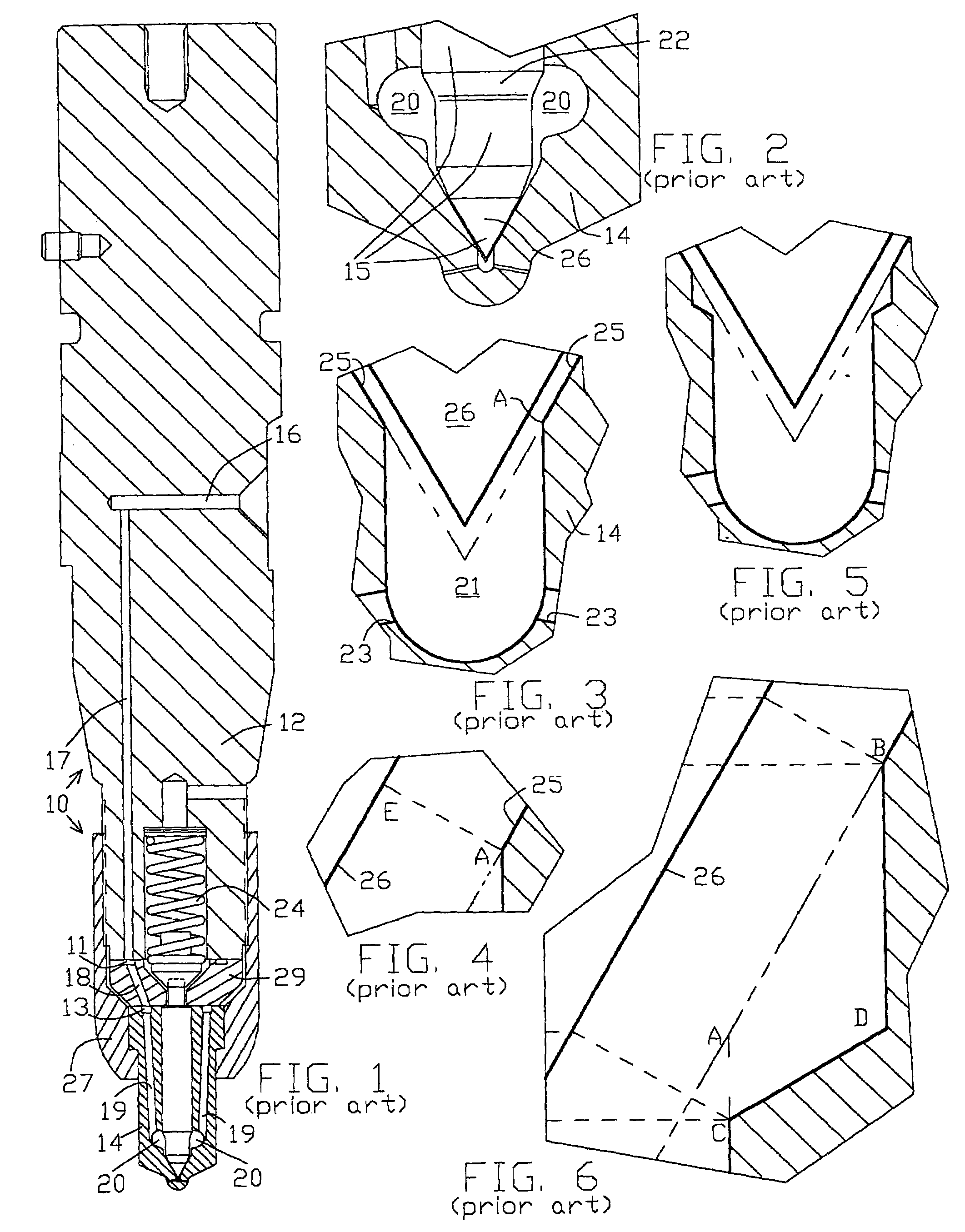
[0023]An injection system employing an ALCO-type injector comprises an injection pump (not shown), high-pressure tubing (not shown) and a nozzle-and-holder assembly 10 shown in FIG. 1. This assembly is secured in the cylinder head of the engine. It includes the holder 12 and the nozzle body 14. The nozzle body, together with the valve stop spacer 29, is clamped on the holder 12 by the nozzle securing nut 27, the latter being threadedly engaged with the holder 12, all as seen in FIG. 1. The high-pressure tubing connects the pump high-pressure fuel delivery outlet to the inlet duct 16.

[0024]When injection pump port closing occurs, a pressure wave is generated delivering fuel through the high-pressure tubing to the inlet duct 16. The pressure wave travels through duct 16, duct 17, annular groove 11 formed in the top face of valve stop spacer 29, ducts 18 (of which there are three, spaced 120° apart, only one being visible in FIG. 1), annular groove 13 formed in the top face of nozzle b...


PUM


Abstract

An annular notch is provided in the body seat associated with the nozzle valve of an ALCO-type diesel injector. The notch extends from (i) an upper edge that is on the seat and is above the imaginary edge that would have been the sac inlet edge had the notch not been provided to (ii) a lower edge below such imaginary edge. The notch has a lowest wall that, at least at the portion of its length where such lowest wall approaches such lower edge, has a given angle-to-vertical of less than 60°.

Description

FIELD OF THE INVENTION[0001]This invention relates generally to fuel injection systems for diesel engines, and particularly to systems employing fuel injectors of the type known as ALCO injectors, originally manufactured by American Bosch for the former American Locomotive Company. Such systems comprise an injection pump, a nozzle-and-holder assembly, and high-pressure tubing joining the pump to the assembly.BACKGROUND OF THE INVENTION[0002]In recent years the diesel engine industry has been under continuing pressure to reduce noxious emissions without unduly sacrificing fuel efficiency, or even while improving fuel efficiency. Engine emissions performance has improved, while maintaining acceptable fuel efficiencies, but pressure for further improvements remains.[0003]An important element in these improvements is the modification of existing designs of diesel injection systems, particularly modification of existing injection nozzle-and-holder assemblies, especially the nozzles. In t...

Claims


Application Information

Patent Timeline
Patent Type & Authority Patents(United States)
IPC IPC(8): F02M61/00F02M61/18
CPCF02M61/1806F02M61/18
Inventor DELUCA, FRANK
Owner BUESCHER DEV
Why Eureka
Try Eureka