
Fan attachment with dynamic out-of-balance equalization

a technology of dynamic out-of-balance equalization and fan attachment, which is applied in the direction of rotors, marine propulsion, and vessel construction, etc., can solve the problems of non-defined dynamic imbalance, inability to securely attach the correction masses required, and inability to compensate dynamic imbalance (couple imbalance) of engine cooling fans, etc., to achieve simple fashion, increase flexural softness, and save energy

Inactive Publication Date: 2005-06-21
ROBERT BOSCH GMBH
View PDF11 Cites 19 Cited by
  • Summary
  • Abstract
  • Description
  • Claims
  • Application Information

AI Technical Summary

Benefits of technology

[0005]Since the dynamic imbalance of an axial fan is clearly dominated by the dynamic imbalance of the axial fan wheel, a two-plane imbalance compensation with the armature and rotor of the electrical drive can be foregone. This, in turn, presents an opportunity for substantial savings, since the processing steps required to obtain two-plan imbalance compensation can now be eliminated entirely. The armature balancing can be foregone entirely, if necessary, by limiting the imbalance compensation to a purely static balancing of an axial fan on the axial fan wheel.
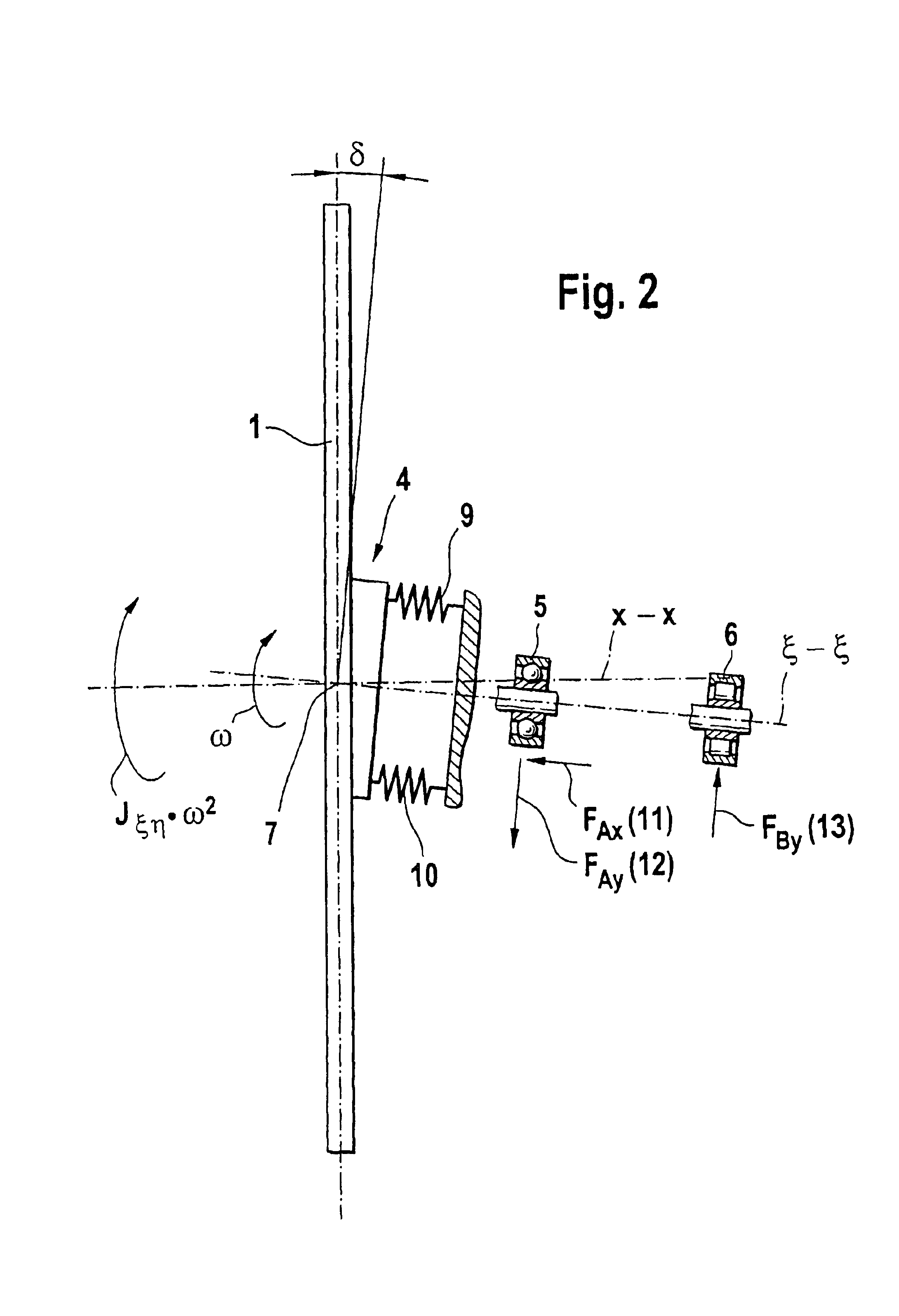
[0006]Due to the soft embodiment of the hub of the axial fan wheel, and / or the connection point of the axial fan wheel with the armature or the rotor shaft, the installation of additional damping systems that take up precious space can be foregone. The modifications of the hub of the axial fan wheel with regard to increasing flexural softness can also be carried out in simple fashion and very cost-effectively within the framework of reworking of engine cooling fans that have already been delivered.

Problems solved by technology

In the case of fans, which often have a flat design, a compensation of the dynamic imbalance (couple imbalance) is not possible at all or only at great expense, since the measurement itself causes problems due to the low flat clearance, and it would not be possible to securely attach the correction masses required to compensate the couple imbalance to the labile fan blades.
As a result, it is accepted practice for engine cooling fans to be delivered with non-defined dynamic imbalance.
Depending on the respective installation situation in the vehicle, the structure-borne noise produced by the dynamic imbalance can result in complaints about vibrations perceived in the passenger compartment.
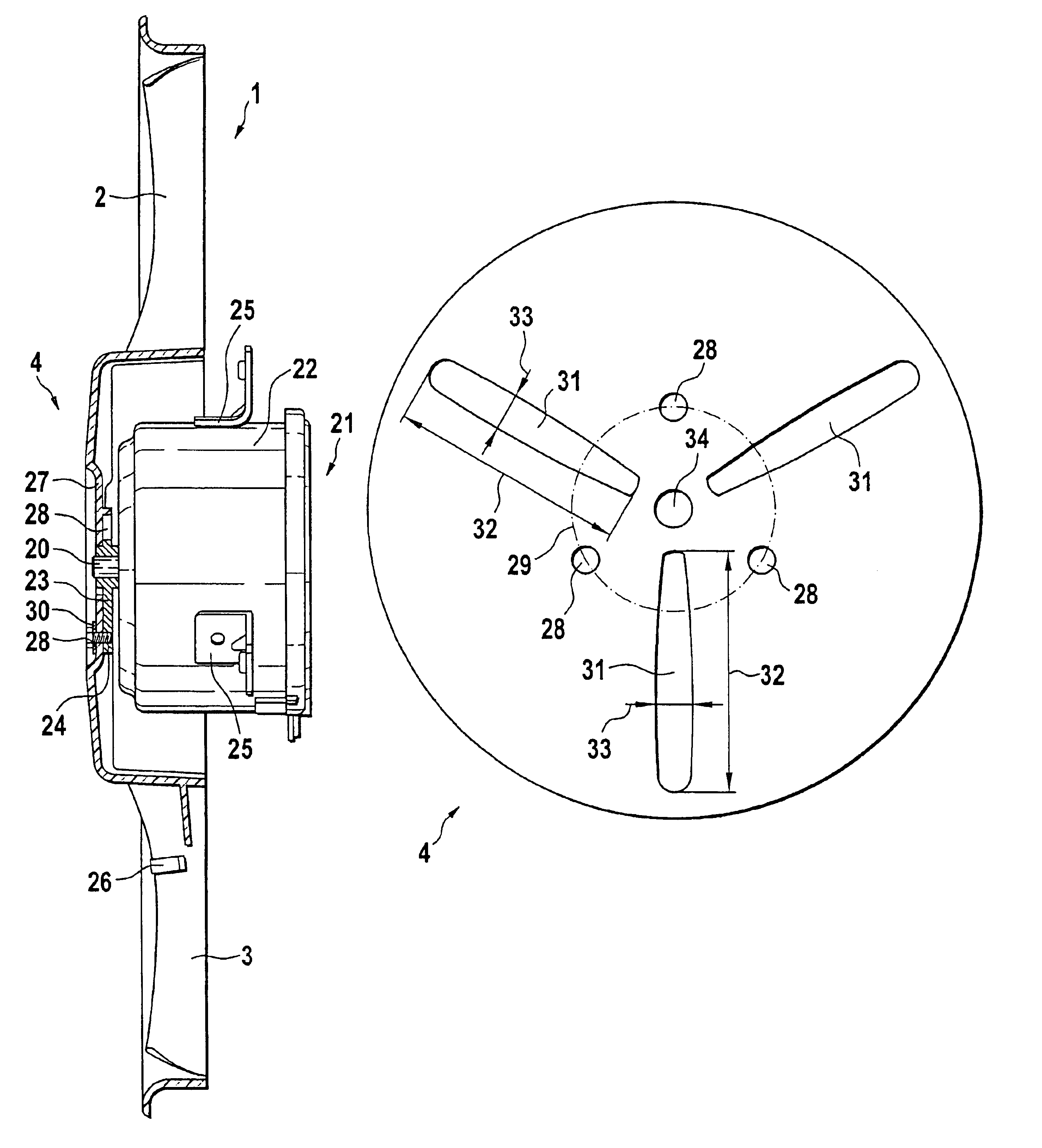
The remaining remedies, such as installing damping elements in the transmission path, or reworking plastic fans in order to reduce their imbalance present upon delivery, are costly and they do not necessarily result in a satisfactory reduction of vibrations.
The inertial forces—static and dynamic imbalances—are caused by inhomogeneous distributions of mass of the rotating rotor / armature assemblies and fans, and by tolerances of form and position relative to the rotation axis of the drive.
A parallel displacement between rotation axis and main axis of inertia, e.g., of a cooling fan having a fan wheel mounted on the armature or rotor shaft results in a static imbalance, while a main axis of inertia tilted relative to the rotation axis can produce a centrifugal moment, the effects of which are comparable to a couple imbalance or dynamic imbalance.

Method used


Image

  • Fan attachment with dynamic out-of-balance equalization
  • Fan attachment with dynamic out-of-balance equalization
  • Fan attachment with dynamic out-of-balance equalization

Examples


Embodiment Construction

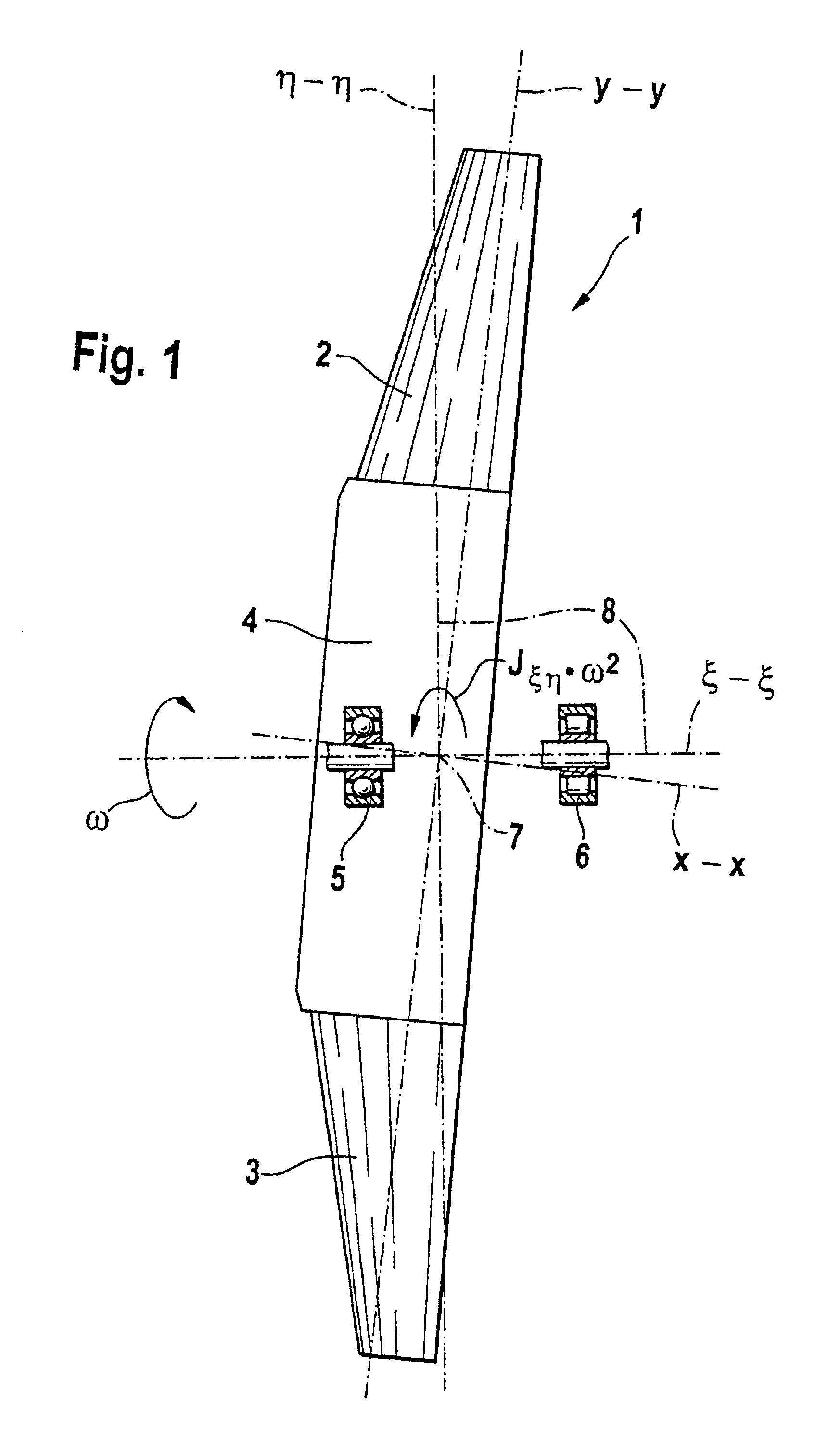
[0018]FIG. 1 shows an axial fan wheel, the main axis of inertia of which is tilted relative to the rotation axis.

[0019]An axial fan wheel 1 comprises fan blades 2 and 3 essentially situated on its outer circumferential region, which said fan blades are mounted on the circumference of a hub region 4. An axial fan wheel 1 according to the depiction in FIG. 1 is preferably manufactured as a plastic injection-molded part. An axial fan wheel of this type is supported on an armature or rotor shaft of an electrical drive not shown in FIG. 1, and it is set in rotation via the electrical drive. The axial fan wheel 1 has a main axis of inertia labelled “x—x” in the depiction according to FIG. 1. Another axis of inertia, labelled “y—y”, extends at a right angle to said main axis of inertia.

[0020]A rotation axis coordinate system 8, characterized by the rotation axis ξ—ξ and the axis η—η extending at a right angle thereto, is displaced relative to the aforementioned axes of inertia x—x and y—y....


PUM


Abstract

The invention is based on an axial fan with a hub region (4, 27) for connecting the axial fan with a driven shaft (20) of an electrical drive (21), whereby the axial fan is statically balanced by means of a balancing weight (26). A flexurally soft connection is formed in the hub region (4, 27) between the axial fan (1) and the driven shaft (20) of an electrical drive (21).

Description

BACKGROUND OF THE INVENTION[0001]Due to environmental considerations, great efforts are being made to eliminate sources of noise in motor vehicles to the greatest extent possible. In addition to tires and internal combustion engines, other acoustic sources are add-on components of the internal combustion engine, e.g., engine cooling fans. With acoustic sources of this nature, a general distinction is made between airborne noise vibrations and the occurrence of structure-borne noise. The occurrence of structure-borne noise can be perceived in the form of inertial force-excited vertical vibrations in the steering wheel of a motor vehicle.PRIOR ART[0002]With engine cooling fans that are common today, a compensation of the static imbalance is usually carried out so that the permissible limit values can be met. In the case of fans, which often have a flat design, a compensation of the dynamic imbalance (couple imbalance) is not possible at all or only at great expense, since the measurem...

Claims


Application Information

Patent Timeline
Patent Type & Authority Patents(United States)
IPC IPC(8): F04D29/66F04D29/32F04D29/26F01P5/02F01P5/04F04D29/38
CPCF04D29/263F04D29/662F04D29/329F04D29/32
Inventor ADRIAN, LUDGER
Owner ROBERT BOSCH GMBH
Learn More