Fuel cell for airship power generation and heating
- Summary
- Abstract
- Description
- Claims
- Application Information
AI Technical Summary
Problems solved by technology
Method used
Image
Examples
first embodiment
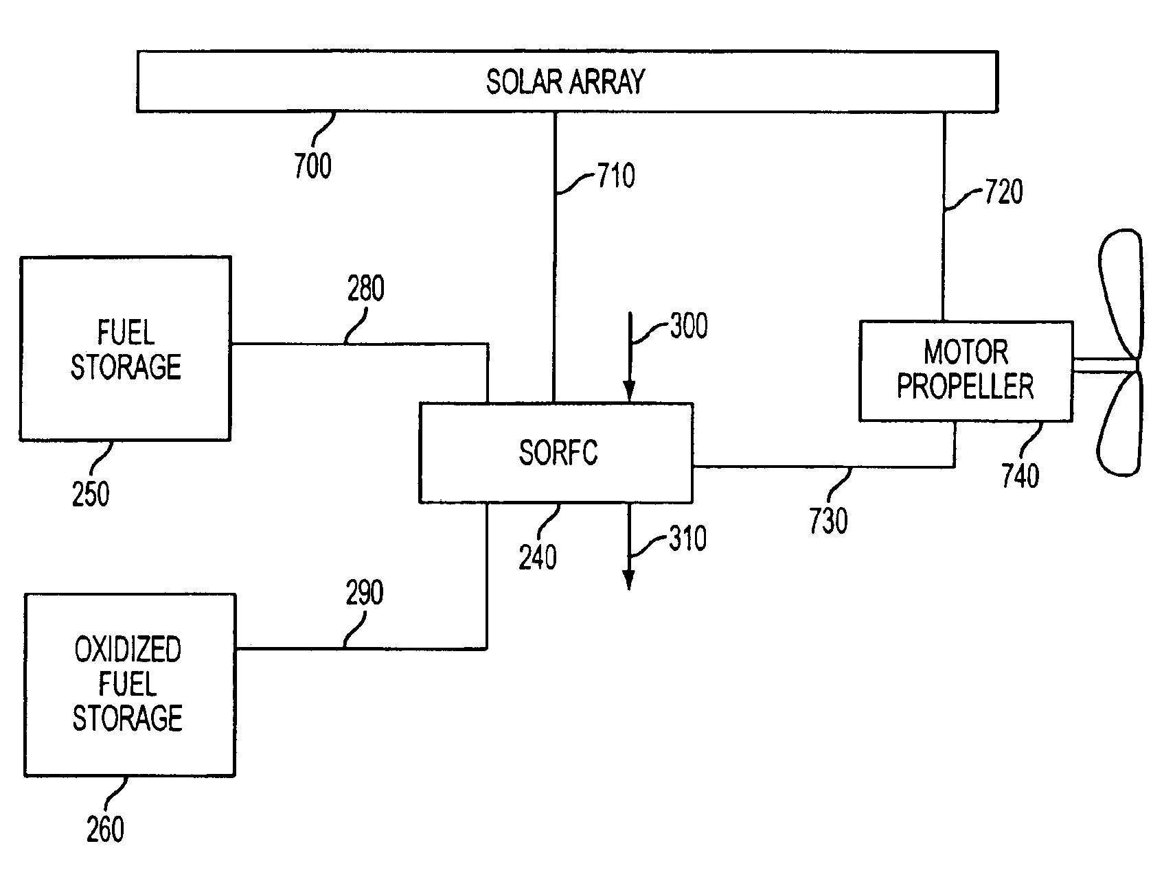
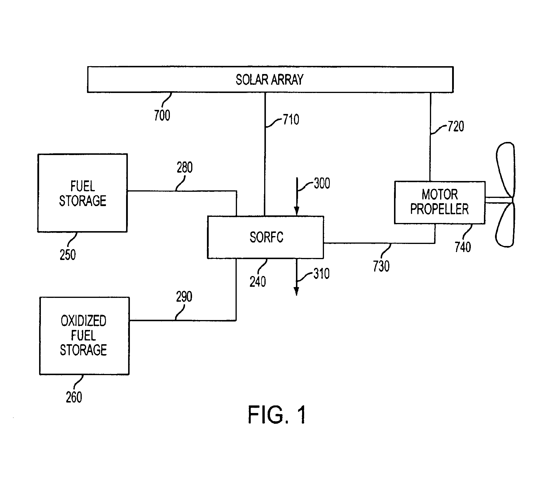
[0033]FIG. 1 illustrates a SORFC system within an airborne vehicle, such as a blimp or a high altitude solar powered unmanned airplane according to a preferred aspect of the If desired, all of the power comes from solar radiation. However, an alternative or an additional power source may also be used. The airborne vehicle contains a body and photovoltaic cells to form a solar array 700. This array converts the solar radiation into DC electricity. During the daytime, when solar radiation is available, a portion of the DC electricity is delivered to the motor propeller system 740 (i.e., an electrical motor which rotates the propeller) and / or to on board electronics from the solar array 700 via electrical cable 720.
[0034]Another portion of the DC electricity is delivered to the SORFC 240 from the solar array 700 via electrical cable 710. At the same time oxidized fuel (i.e., water) is delivered to the SORFC 240 from oxidized fuel storage vessel 260 via fluid conduit 290. Within SORFC ...
second embodiment
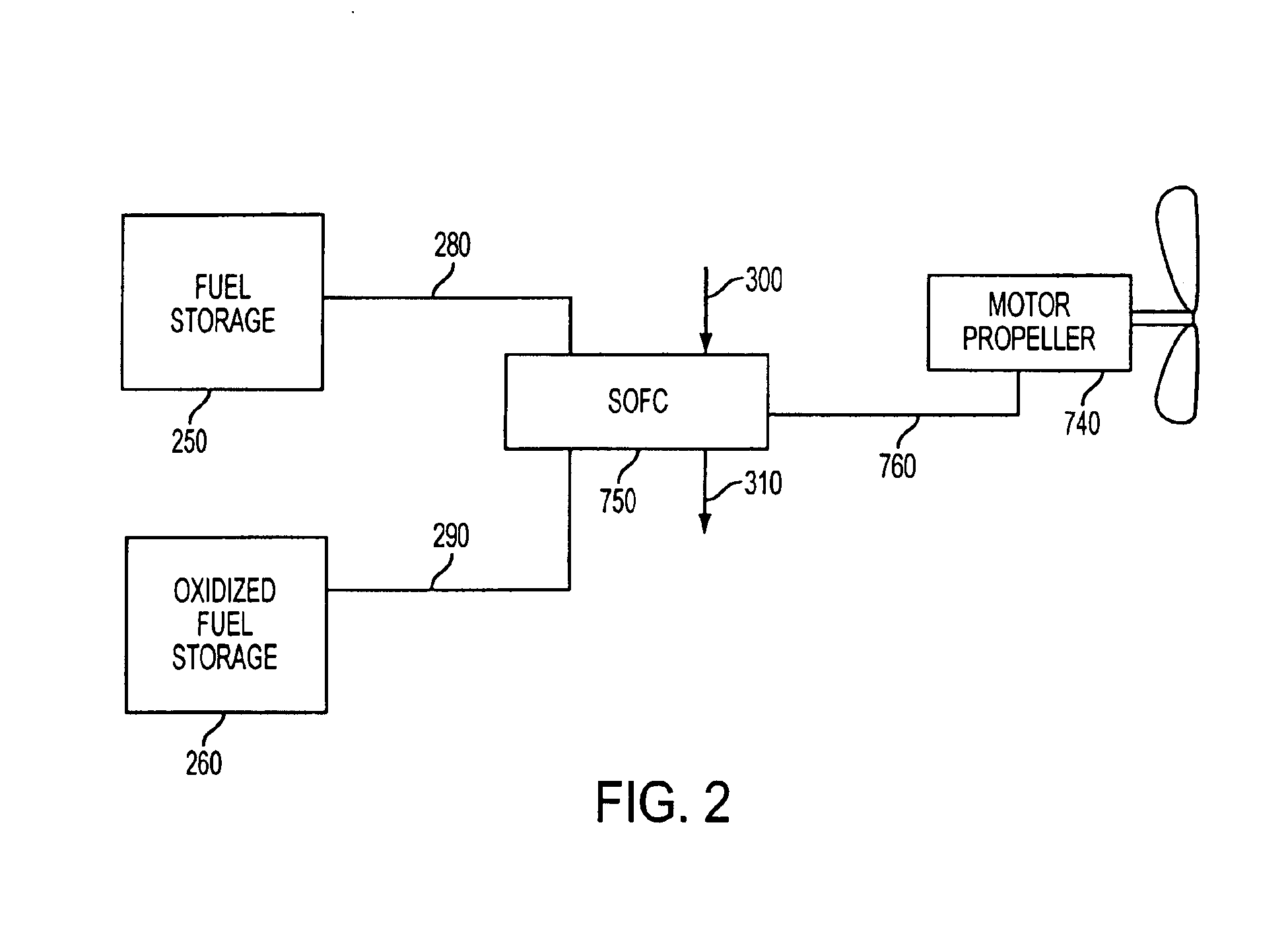
[0040]FIG. 2 illustrates a SOFC system within an airship according to a preferred aspect of the Fuel (preferably hydrogen) is delivered from fuel storage vessel 250 to the SOFC 750 via fluid conduit 280. Simultaneously, ambient air oxidant oxygen is supplied to SOFC 750 via fluid conduit 300. Within SOFC 750, reactions produce DC electricity and oxidized fuel (water). The oxidized fuel is delivered from the SOFC 750 to the oxidized fuel storage vessel 260 via fluid conduit 290. If stealth characteristics are not important in the airship, then the oxidized fuel may be vented into the atmosphere and the storage vessel 260 and conduit 290 may be omitted. The depleted oxidizer (i.e., oxygen depleted air) is vented into the atmosphere through conduit 310. The DC electricity is delivered from the SOFC 750 to the motor propeller system 740 via electrical cable 760 providing thrust for the airplane until the fuel is exhausted.
[0041]Third Preferred Embodiment
[0042]FIG. 3 illustrates the use...
third embodiment
[0052]Preferably, the controller 24 provides heat from the fuel cell 16 to the envelope 12, such as by opening the valve and / or operating the blower, in response to a sensed condition. In a preferred aspect of the third embodiment, the airship 10 also contains one or more condition sensors 26 which are operatively connected to (i.e., in electrical, optical or radio communication with) the controller 24.
[0053]In one preferred aspect of the third embodiment, the sensor 26 comprises an altitude detector adapted to detect an altitude of the airship. The controller 24 is adapted to selectively provide heat from the fuel cell 16 to the gas envelope 12 to elevate the airship to a different altitude if the detected altitude is below a desired altitude.
[0054]In another preferred aspect, the sensor 26 is a temperature detector adapted to detect an ambient temperature adjacent to the airship 10. The controller 24 is adapted to selectively provide heat from the fuel cell to the gas envelope if ...
PUM
 Abstract
Description
Claims
Application Information
 - R&D
- Intellectual Property
- Life Sciences
- Materials
- Tech Scout
- Unparalleled Data Quality
- Higher Quality Content
- 60% Fewer Hallucinations
Browse by: Latest US Patents, China's latest patents, Technical Efficacy Thesaurus, Application Domain, Technology Topic, Popular Technical Reports.
© 2025 PatSnap. All rights reserved.Legal|Privacy policy|Modern Slavery Act Transparency Statement|Sitemap|About US| Contact US: help@patsnap.com


