Scintillation detector, system and method providing energy and position information

Inactive Publication Date: 2005-06-21
SAINT GOBAIN CERAMICS & PLASTICS INC
View PDF14 Cites 42 Cited by
  • Summary
  • Abstract
  • Description
  • Claims
  • Application Information

AI Technical Summary

Benefits of technology

[0033]According to still another and more general aspect of the invention, a scintillation device comprises a scintillator and a reflector disposed at a surface of the scintillator for reflecting scintillation light, wherein the reflector is ma

Problems solved by technology

Scattered radiation degrades the quality of the image.
Loss of light without sensing reduces the energy information available.
There are also other, less helpful reflections in the optical system.
Multiple reflections of the favorable and unfavorable types may occur before light is collected and sensed, or finally lost.
Also, if the light spreads among too many PMT's, the signal amplitude in each will below and therefore too easily influenced by electronic noise.
Significant defects in the crystal or the glass will cast shadows or interrupt or alter the transport of light and thereby alter the quality of, or introduce image artifacts into, the resulting images.
Typical existing gamma camera detector assemblies like those described above have the disadvantage that their effective use requires large, highly transparent crystals and associated glass window pieces with a high degree of optical perfection over large areas.
These gamma camera detectors also have the disadvantage that all the PMT's are optically connected to the entire crystal, so that radiation events anywhere on the face of the crystal activate large areas of the sensing and electronics analysis system.
While involving fewer PMT's improves rate capability, other properties may suffer.
Too few PMT's leads to light transmission beyond the sensing area in use being lost for position or energy determination purposes, or both.
This technique has count rate advantages, but also has cost disadvantages in that many more PMT's are required to achieve the same spatial resolution as is available from a conventional gamma camera.
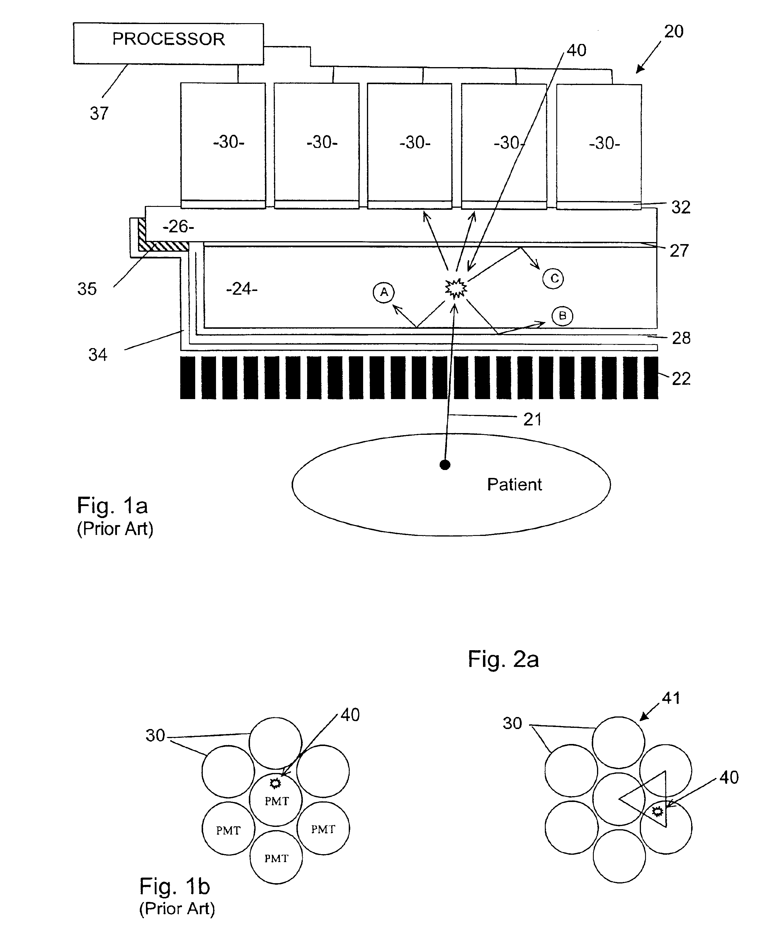
The present gamma cameras cannot provide position infor

Method used


Image

  • Scintillation detector, system and method providing energy and position information
  • Scintillation detector, system and method providing energy and position information
  • Scintillation detector, system and method providing energy and position information

Examples


Embodiment Construction

[0050]Aside from the differences described below, a detector system and method (particularly a gamma camera and its method of operation) according to the several below described embodiments of the invention may be the same as the above-described prior art detector system shown in FIGS. 1a and 1b. Accordingly, like reference numerals are used below to denote the same or similar elements.

[0051]In accordance with one preferred embodiment of the novel invention, a gamma camera is constructed and operated so that signal amplitude and event position information is obtained from a cluster of three mutually-adjoining light sensors by the use of triangular coordinate mathematics. By this approach, the number of light sensor's involved in position and energy determination for a particular event is reduced from the number involved in prior arrangements as discussed above principally to only three light sensor's, as is shown schematically in FIGS. 2a, 3a, 3b, 3c, 3d, and 3e. The three light sen...


PUM


Abstract

A radiation detector, in particular a gamma camera, is constructed and operated in such a fashion that only a predetermined number of light sensors (such as PMT's) adjoining each other in a cluster are used to generate a signal with amplitude and event position information. The camera may also use an array of individual scintillation elements (crystals) in place of a single crystal, with certain advantages obtained thereby. According to another aspect of the invention, there is a reflector sheet that defines an array of apertures through which scintillation light can pass from the scintillation crystal to a plurality of light sensors optically coupled to an optical window in an array corresponding to the array of apertures in the reflector.

Description

RELATED APPLICATION DATA[0001]This application claims the benefit of provisional application No. 60 / 281,284 filed on Apr. 3, 2001 and entitled “Scintillation Detector, System and Method Providing Energy & Position Information,” which is hereby incorporated herein by reference in its entirety.FIELD OF THE INVENTION[0002]The invention described herein relates generally to scintillation detectors sensitive to ionizing radiation, to a method for performing radiation-based measurements, and also to methods of manufacture for such scintillation detectors. The scintillation detectors and methods are particularly useful for imaging in nuclear medicine applications, but may have use in other applications where the radiation energy passing into the scintillator or the position of interaction of the radiation with the scintillator are of interest.BACKGROUND OF THE INVENTION[0003]Scintillation detectors have been employed in medical imaging applications for some years and are embodied in device...

Claims


Application Information

Patent Timeline
IPC IPC(8): G01T1/164G01T1/00G01T1/202
CPCG01T1/1642G01T1/202G01T1/1647
Inventor SCHREINER, ROBERT S.WHITE, JOHN A.MAYHUGH, MICHAEL R.MATARAZA, GEORGEROZSA, CSABA M.HERR, DANIEL J.
Owner SAINT GOBAIN CERAMICS & PLASTICS INC
Why Eureka
Try Eureka