Tunable filter for optical add/drop module

Inactive Publication Date: 2005-06-21
OPTOPLEX CORP
View PDF1 Cites 18 Cited by
  • Summary
  • Abstract
  • Description
  • Claims
  • Application Information

AI Technical Summary

Benefits of technology

[0016]According to yet another aspect of the invention, retro-reflecting components are positioned in the optical paths of the beams that emerge from the tunable thin-film filter. The beams are retro-directed along lines parallel to their prior optical paths and traverse the thin-film filter component, the half-way plate, and the polarizing beam splitter for a second time in reverse fashion. The beams' second passing through the tunable filter results in compensation of the original lateral shift introduced by the tunable filter, as

Problems solved by technology

This in turn greatly reduces the polarization dep

Method used


Image

  • Tunable filter for optical add/drop module
  • Tunable filter for optical add/drop module
  • Tunable filter for optical add/drop module

Examples


Embodiment Construction

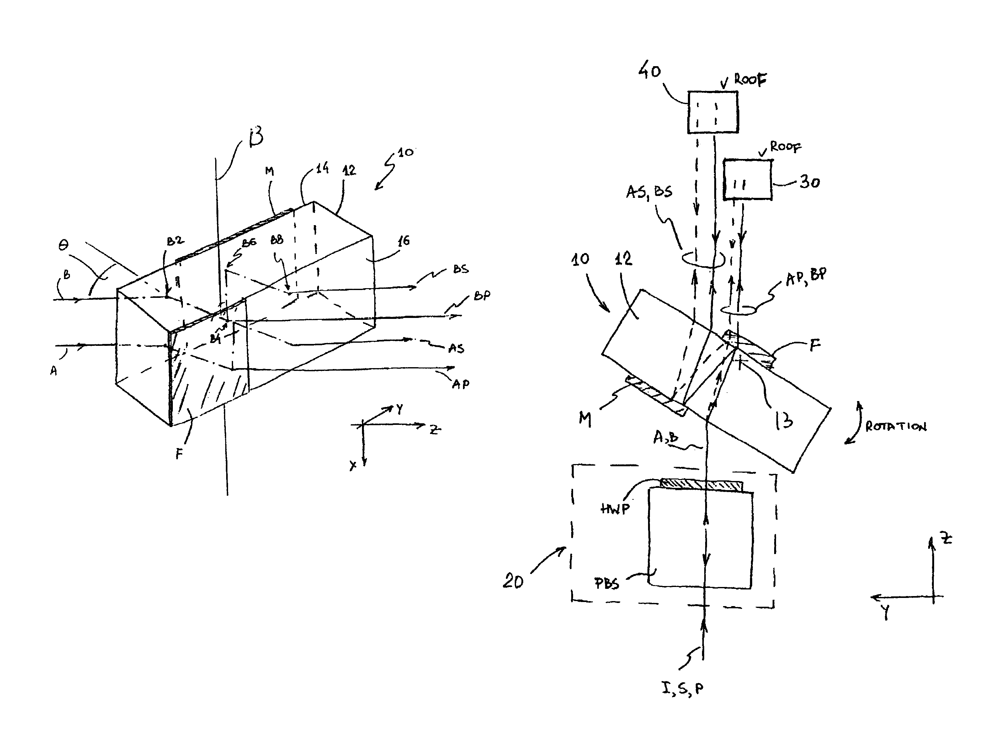
[0029]The invention is directed at providing a tunable thin-film filter system which overcomes the drawbacks of the prior-art configurations. Specifically, the dependence of the filter's spectral performance on the state of polarization of the input light and the spatial deviations of the channel beams due to filter rotation are eliminated. In addition, stronger spectral filtering of the input light is provided in a cost-efficient way.

[0030]In the following description of optical trains (which in the context of this invention are defined as sets of one or more optical elements performing the required optical functions), the loss of light on residual reflections at interfaces, on absorption in materials, and on scattering is of little relevance to the subject matter of the invention; thus, a discussion of these residual losses is omitted. In practice, they can be dealt with in conventional manner by providing an adequate level of AR-coating on corresponding optical surfaces and by ch...


PUM


Abstract

A tunable filter includes a polarizing beam splitter and a half-wave plate that produce two equally polarized beams from an arbitrarily polarized input light. The polarized beams are directed toward a tunable component that consists of an optical substrate coated with a filter and a reflective element on its back and front surface, respectively. The pass and stop beams emerging from the tunable component are retro-reflected by roof structures and passed again through the filter. As a result of this combination of components, the filter's performance is not dependent on polarization and the filter's output channels are not shifted or deviated by tuning.

Description

RELATED APPLICATIONS[0001]This application is based on U.S. Provisional Ser. No. 60 / 362,650, filed Mar. 8, 2002.BACKGROUND OF THE INVENTION[0002]1. Field of the Invention[0003]This invention pertains to the general field of optical filters and, in particular, to a tunable optical filter with improved spectral performance and undeviated pass and stop beams.[0004]2. Description of the Prior Art[0005]Optical filters are widely used as components of optical systems. In particular, they are employed in optical communication systems, where information is transmitted along the same optical path at different wavelengths λ of light (channels). In order to retrieve information contained in a particular channel, the signal wavelengths have to be spectrally separated. Similarly, in order to add a particular channel to the stream of optical information, a spectral addition of a particular wavelength is often required. These functions have been traditionally accomplished with the use of optical a...

Claims


Application Information

Patent Timeline
IPC IPC(8): G02B27/00G02B6/34
CPCG02B6/2713G02B6/29395G02B6/29383G02B6/29367G02B6/2766
Inventor HSIEH, YUNG-CHIEHAI, CHIAYULI, HONGSONG, DAR-YUAN
Owner OPTOPLEX CORP
Why Eureka
Try Eureka