Signal acquisition system for spread spectrum receiver

a spread spectrum receiver and signal acquisition technology, applied in the direction of transmission, electrical equipment, etc., can solve the problems of preventing the acquisition system from operating, the signal-to-noise ratio is low, and the accuracy of the adjustment of different timings cannot be achieved. , to achieve the effect of improving the sensitivity of the acquisition system and lengthening the integration tim

Inactive Publication Date: 2005-06-21
QUALCOMM INC
View PDF24 Cites 82 Cited by
  • Summary
  • Abstract
  • Description
  • Claims
  • Application Information

AI Technical Summary

Benefits of technology

[0030]In another embodiment of the invention, the device also comprises an non-coherent integrator for integrating said absolute values or estimates of the absolute values of the correlation samples over an integration period that is longer than the length in time of the matched filter. This way, in the invention, the matched filter and the coherent integrator are able to carry out coherent integration as long as possible, and thereafter lengthen the integration time by non-coherent integration. An non-coherent integrator can be implemented by the same kind of simple structure as a coherent integrator.
[0031]According to still another embodiment of the invention, the device comprises a controller

Problems solved by technology

In the structures of generally known matched filters, the timing of a reference signal and an incoming signal is fixed at the planning stage, and cannot thus be adjusted accurately for different timings.
This causes problems for tracking signals having a low signal-to-noise ratio, since the integration time required by them is long.
If the inaccuracy of the frequency exceeds 1/Tl, the timing of the code changes more than one chip during integration, which prevents the acquisition system from operating.
The integration time of a DS-SS acquisition system is also limited by the modu

Method used


Image

  • Signal acquisition system for spread spectrum receiver
  • Signal acquisition system for spread spectrum receiver
  • Signal acquisition system for spread spectrum receiver

Examples


Embodiment Construction

[0040]In the present document, a complex signal refers to a signal composed of two signal components obtained by multiplying a received signal by a carrier replica and its 90° phase-shifted version. In other words, if the received signal r(t) is of the form:

r(t)=I(t)·cos(ωct+θ0)−Q(t)·sin(ωct+θ0)

wherein ωc, t and θ0 represent carrier frequency, time and an unknown constant phase term at time 0. I(t) and Q(t) constitute the above complex signal, which is expressed mathematically as:

z(t)=A(t)·ejφ(t)=A(t)·cos(φ(t))+j·A(t)·sin(φ(t))=I(t)+j·Q(t)

Hence;

r(t)=Re(z(t)·ej(ωc(t)+θ0))=Re(A(t)·ejφ(t)·ej(ωc(t)+θ0))

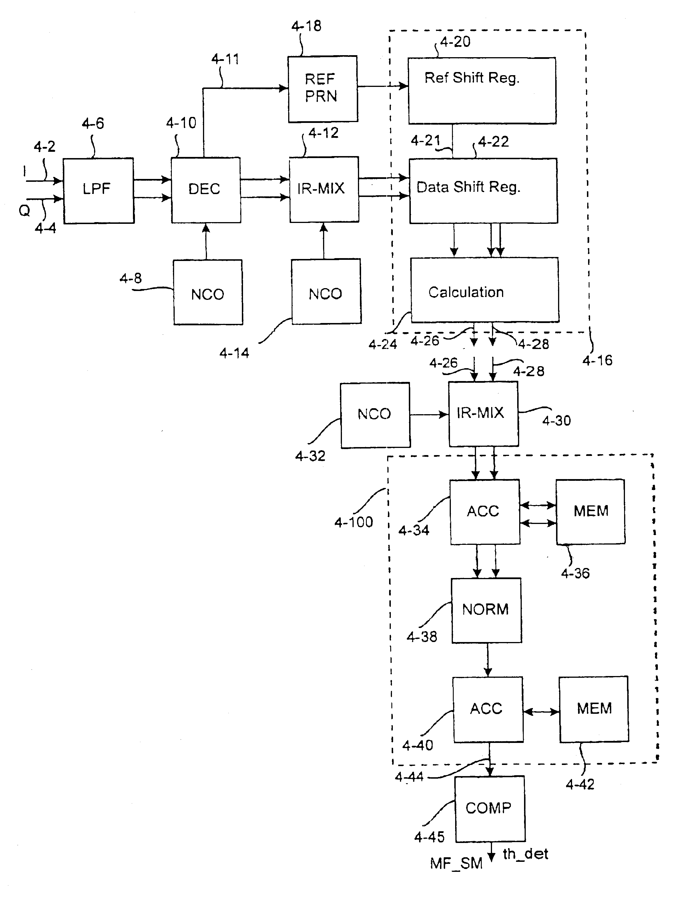
[0041]The acquisition system according to the primary embodiment of the invention comprises four basic blocks: a data path block, a control block, a state machine and an I / O block. The data path block and state machine are described in more detail below.

[0042]Data Path Block

[0043]The data path block of a matched filter constitutes the core of an acquisition system and comprises, not o...


PUM


Abstract

A device for detecting a demodulated signal received by a spread spectrum receiver and converted into digital samples. The device is characterized by a matched filter for calculating the correlation between an incoming signal and at least one reference signal, an oscillator for generating a sampling frequency, and a sampling circuit for re-sampling the demodulated digital sample signal at the sampling frequency, which is such that the timing of samples of the references signals of the matched filter corresponds to the timing of a sample signal going from the sampling circuit to the matched filter. The device also includes a multiplier in which the sample signal is multiplied by a carrier replica generated locally before the sampling circuit or thereafter, to remove the carrier from the sample signal.

Description

BACKGROUND OF THE INVENTION[0001]The invention relates to a spread spectrum receiver and particularly to an acquisition system for a signal received by the receiver.[0002]A spread spectrum system is a telecommunications system in which the bandwidth used for transmitting a signal is substantially wider than is required for the data to be transmitted. The spectrum of the signal is spread in a transmitter by means of a pseudo-random spreading code, which is independent of the original data.[0003]In direct sequence spread spectrum systems (DS-SS), a spectrum is spread to the available bandwidth by shifting the phase of the carrier in accordance with a pseudo-random spreading code. The bits of a spreading code are usually called chips as distinct from actual data bits.[0004]FIG. 1 shows a block diagram illustrating a direct sequence-based spread spectrum system. In the system, a signal of a data source 1-2 is first modulated in a data modulator 1-4 of a transmitter 1-1 whereupon a compl...

Claims


Application Information

Patent Timeline
IPC IPC(8): H04B1/707
CPCH04B1/708H04B1/7093
Inventor EEROLA, VILLERITONIEMI, TAPANI
Owner QUALCOMM INC
Why Eureka
Try Eureka