
Brake plate and method and apparatus for manufacturing same

a technology of brake plate and friction pad, which is applied in the direction of furniture joining, metal rolling arrangement, planing/slotting machine, etc., can solve the problems of friction pad breaking, difficulty in attaching and/or retaining friction pads, and consequent increase in costs, so as to increase the structural strength of the plate, improve the bond, and avoid the effect of increasing the cost of plate production

Inactive Publication Date: 2005-06-28
NUCAP IND
View PDF34 Cites 36 Cited by
  • Summary
  • Abstract
  • Description
  • Claims
  • Application Information

AI Technical Summary

Benefits of technology

[0013]It is an object of the invention to provide a plate which provides an improved bond between it and the friction pad, as well as increasing the structural strength of the plate, without increasing the cost of producing the plate. In addition, it is an object of the invention to provide a method and apparatus for manufacturing the plate which reduces time and cost by requiring fewer manufacturing steps, while at the same time retaining the structural strength of the backing plate.
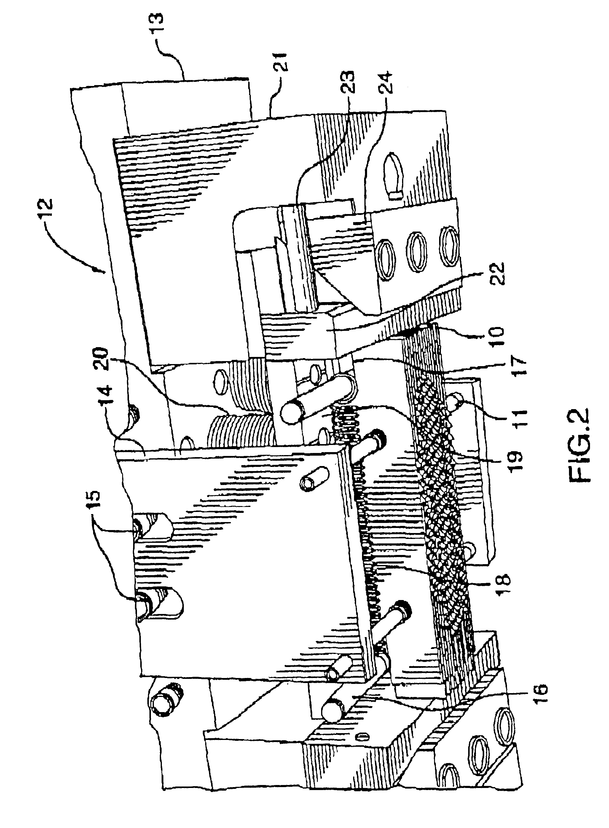
[0041]The first and second sliding members preferably impact the bottom portion of the press prior to the knives impacting the contact surface, thereby causing the knives to move generally parallel to the contact surface prior to impact of the knives against the contact surface. The first and second sliding members preferably impact the bottom portion of the press substantially simultaneously with the knives impacting the contact surface, thereby causing the knives to move generally parallel to the contact surface substantially simultaneously with impact of the knives against the contact surface.

Problems solved by technology

The need to use high speed low cost manufacturing methods often results in irregularities in the plate which may lead to difficulties in attaching and / or retaining the friction pad on the plate during braking, when the friction pad is in contact with the rapidly turning brake rotor, or even during the pre-installation handling of the brake pad assembly.
One disadvantage of the riveting process is that it creates a rigid bond between the plate and the friction pad, which can, as result of a sudden impact, lead to breaking of the friction pad.
Furthermore, this process often requires one or more additional manufacturing steps with a consequent increase in cost.
In addition, when the friction pad is worn down over time, the rivets become exposed and rub against the brake rotor, causing scoring on the rotor which is costly to repair.
The plate is subjected to a number of forces, such as the jarring of the moving vehicle, as well as vibration caused by the rotor and noise.
The problem with the prior art processes and plates is that features, such as holes and bosses, stamped into the plate often provided insufficient shear and / or tensile strength in the bond between the friction pad and plate.
When additional features are stamped into the plate to increase bond strength, additional manufacturing steps are required, adding to the cost.
The most common prior art features stamped into plates are circular holes, These holes often provide unsatisfactory results because, during the molding process, the pre-form cake does not completely fill all of the holes, which in turn, leads to deficient bonding between the plate and the pre-form.
The incomplete hole fills can are clearly visible, and often raise quality concerns when inspected by buyers.
The incomplete hole fills also have an aesthetically displeasing appearance, which can also make them less attractive to customers.
These additional manufacturing steps have the added disadvantage of increasing the cost of manufacturing the disc brake.
Furthermore, the holes stamped by prior art processes reduce structural strength of the plate, and make it more vulnerable to the various forces acting on it.
These forces may distort the shape of the plate, leading to uneven wear on the friction pad, or can lead to structural failure of the plate.
Another problem with brake plates is caused by the heat generated by friction.
Rust can then form between the plate, which leads to noise and brake failure.

Method used


Image

  • Brake plate and method and apparatus for manufacturing same
  • Brake plate and method and apparatus for manufacturing same
  • Brake plate and method and apparatus for manufacturing same

Examples


Embodiment Construction

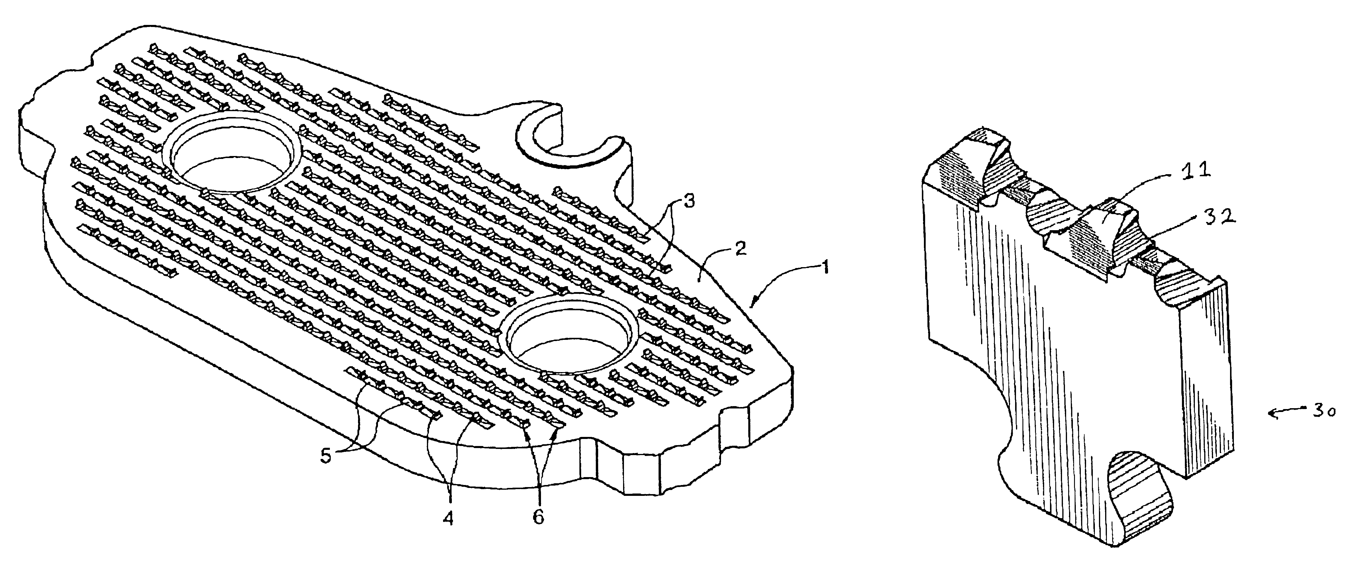
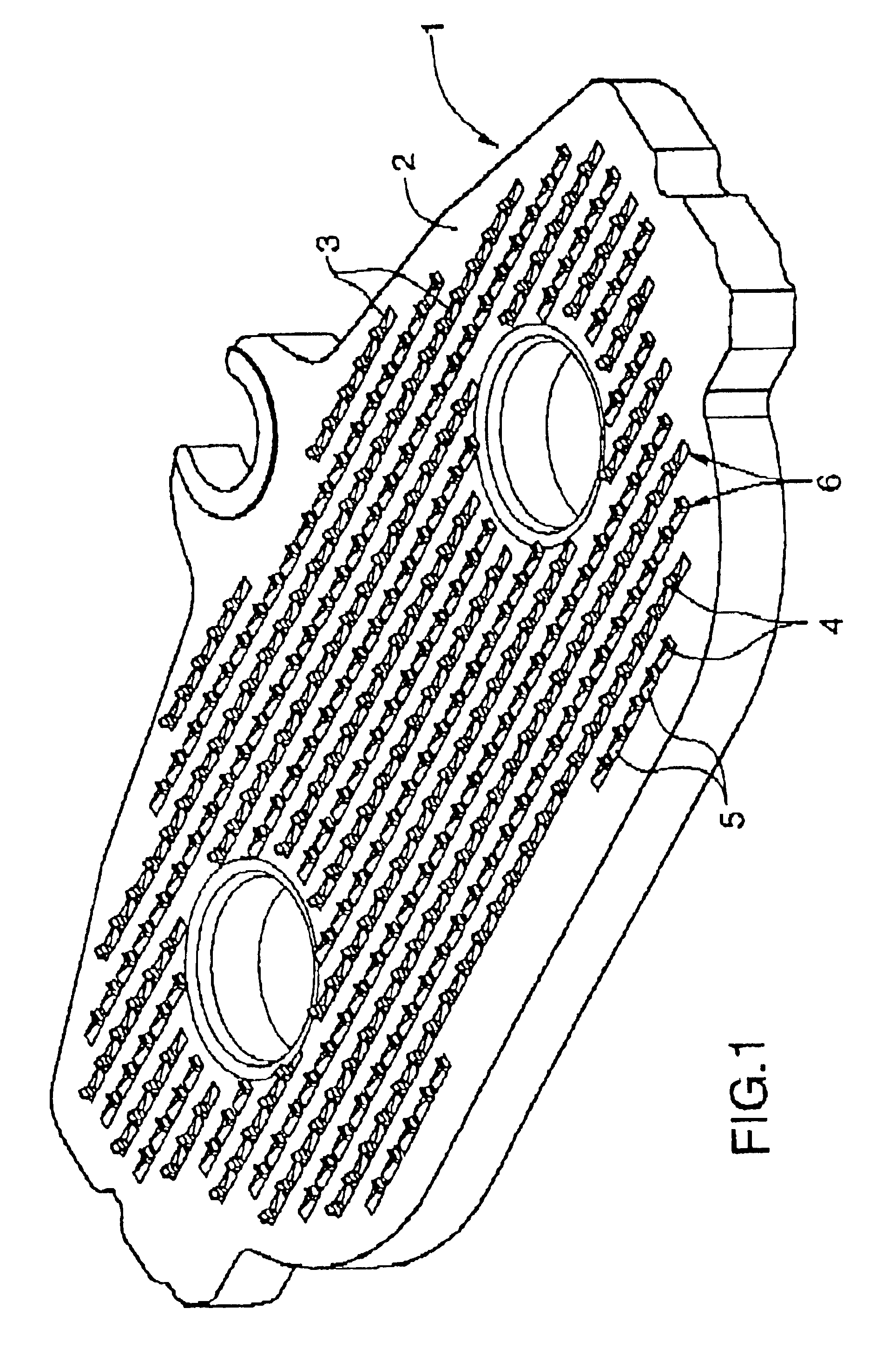
[0060]The invention is a plate for holding a friction material in a brake assembly. The plate preferably comprises:

[0061](a) a contact surface for attaching the friction material to the plate,

[0062](b) a second surface opposing the contact surface;

[0063](c) a plurality of retaining structures formed on the contact surface, each retaining structure comprising a projecting member extending from a point between the contact surface and the second surface, so that the member extends outwardly from the contact surface for engagement with the friction material.

[0064]The retaining structure may further comprise a depression surface abutting the projecting member, the depression surface extending into the contact surface.

[0065]The brake plate, as well as the process and apparatus for manufacturing same according to the present invention are useful in the field of manufacturing of vehicle brake parts. The plate is useful in brakes for any motor vehicle, such as cars, trucks, airplanes, trains...


PUM

PropertyMeasurementUnit
heightaaaaaaaaaa
distanceaaaaaaaaaa
distanceaaaaaaaaaa

Abstract

The invention is a plate for holding a friction material in a brake assembly. The plate preferably comprises a contact surface for attaching the friction material to the plate, a second surface opposing the contact surface; and a plurality of retaining structures formed on the contact surface, each retaining structure comprising a projecting member extending from a point between the contact surface and the second surface, so that the member extends outwardly from the contact surface for engagement with the friction material.

Description

[0001]This is a divisional of application Ser. No. 09 / 507,065, filed on Feb. 18, 2000, now U.S. Pat. No. 6,464,047, which is hereby incorporated herein by reference.TECHNICAL FIELD[0002]This invention relates to brakes, and in particular to an improved brake plate, as well as a method and apparatus for manufacturing the plate.BACKGROUND ART[0003]The number of motor vehicles has increased greatly in recent years. There is an interest in methods of reducing the cost of manufacturing brakes and replacement parts on the part of both motor vehicle manufacturers and suppliers of parts for brakes. This increased use has also led to a significant increase in the after-market for brake replacement and repair. Brakes are also in increasing demand for motor vehicles such as airplanes, trains, bicycles, all terrain vehicles and motorcycles.[0004]Brakes, as currently manufactured, combine two main parts, namely a plate (often called a backing plate) and a friction pad. The plate is mounted in a ...

Claims


Application Information

Patent Timeline
Patent Type & Authority Patents(United States)
IPC IPC(8): B23D79/00B23D3/00F16D69/00F16D69/04B21J5/12F16F9/00
CPCB21J5/12B23D3/00B23D79/00F16D69/04F16D69/0408F16D2069/0441Y10T29/4998F16D2069/0491F16D2250/0007Y10T29/49886Y10T403/475Y10T29/49986Y10T403/472F16D2069/0483B21J5/068
Inventor ARBESMAN, RAY
Owner NUCAP IND
Learn More