Method for regulating the electrical power applied to a substrate during an immersion process

a technology of electrical power and immersion process, which is applied in the direction of machining electric circuits, manufacturing tools, electric circuits, etc., can solve the problems of increasing the difficulty of filling void-free interconnect features via conventional metallization techniques, increasing the resistance of conductive paths, and increasing the difficulty of plating irregularities

Inactive Publication Date: 2005-06-28
APPLIED MATERIALS INC
View PDF125 Cites 11 Cited by
  • Summary
  • Abstract
  • Description
  • Claims
  • Application Information

AI Technical Summary

Benefits of technology

[0009]Embodiments of the invention further provide a method for maintaining a loading bias having a constant current density during an immersion process. Embodiments generally include sensing a pivotal position of a lid member supporting a substrate during an immersion process, and determining a present total immersed area from the sensed pivotal position. The method can further include determining a load bias current that will generate the constant current density, and adjusting a current supplied to the substrate to correspond with the load bias current. Additionally, the steps of sensing, determining the current, determining the load bias, and adjusting can be at predetermined time intervals during the immersion process.
[0010]Embodiments of the invention further provide a m...

Problems solved by technology

However, as interconnect sizes decrease and aspect ratios increase, void-free interconnect feature fill via conventional metallization techniques becomes increasingly difficult.
However, one challenge associated with ECP processes is that the plating solutions, which are generally acidic, may chemically etch the seed layer during the process of immersing the substrate in the plating solution.
Inasmuch as seed layers are generally relatively thin conductive layers, the chemical etching that may take place during the immersion process may result in conductive discontinuities in the seed layer, which may cause plat...

Method used


Image

  • Method for regulating the electrical power applied to a substrate during an immersion process
  • Method for regulating the electrical power applied to a substrate during an immersion process
  • Method for regulating the electrical power applied to a substrate during an immersion process

Examples


Embodiment Construction

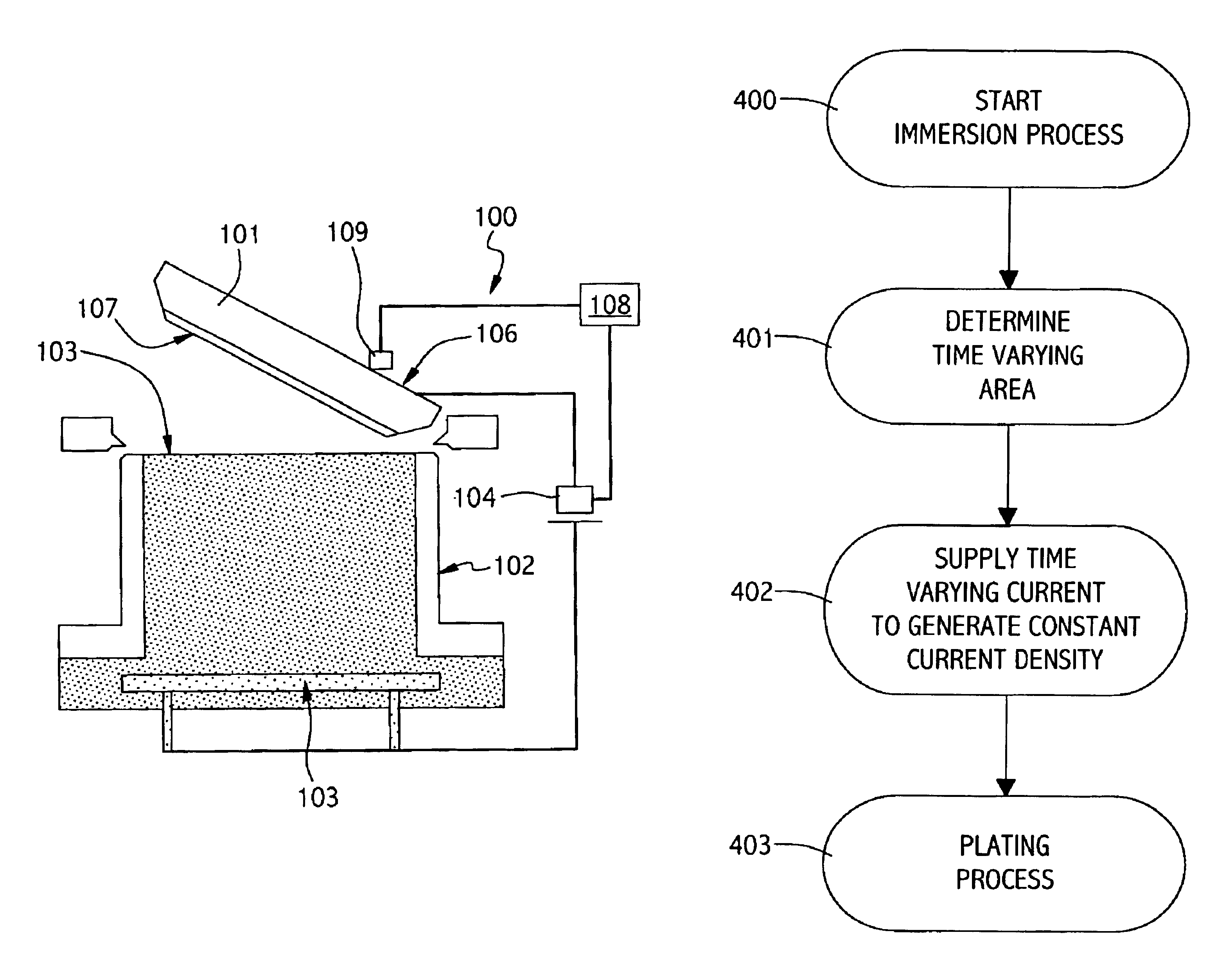
[0017]The present invention generally provides an apparatus and method for controlling the voltage or current applied to a substrate being immersed in an electrolyte solution. The voltage or current may be controlled in a manner that provides a constant current density across the surface of the substrate as the area of the substrate contacting the electrolyte increases during the immersion process. The application of a constant current density to the substrate surface operates to prevent seed layer irregularities and / or discontinuities that may facilitate plating uniformity problems in subsequent processing steps.

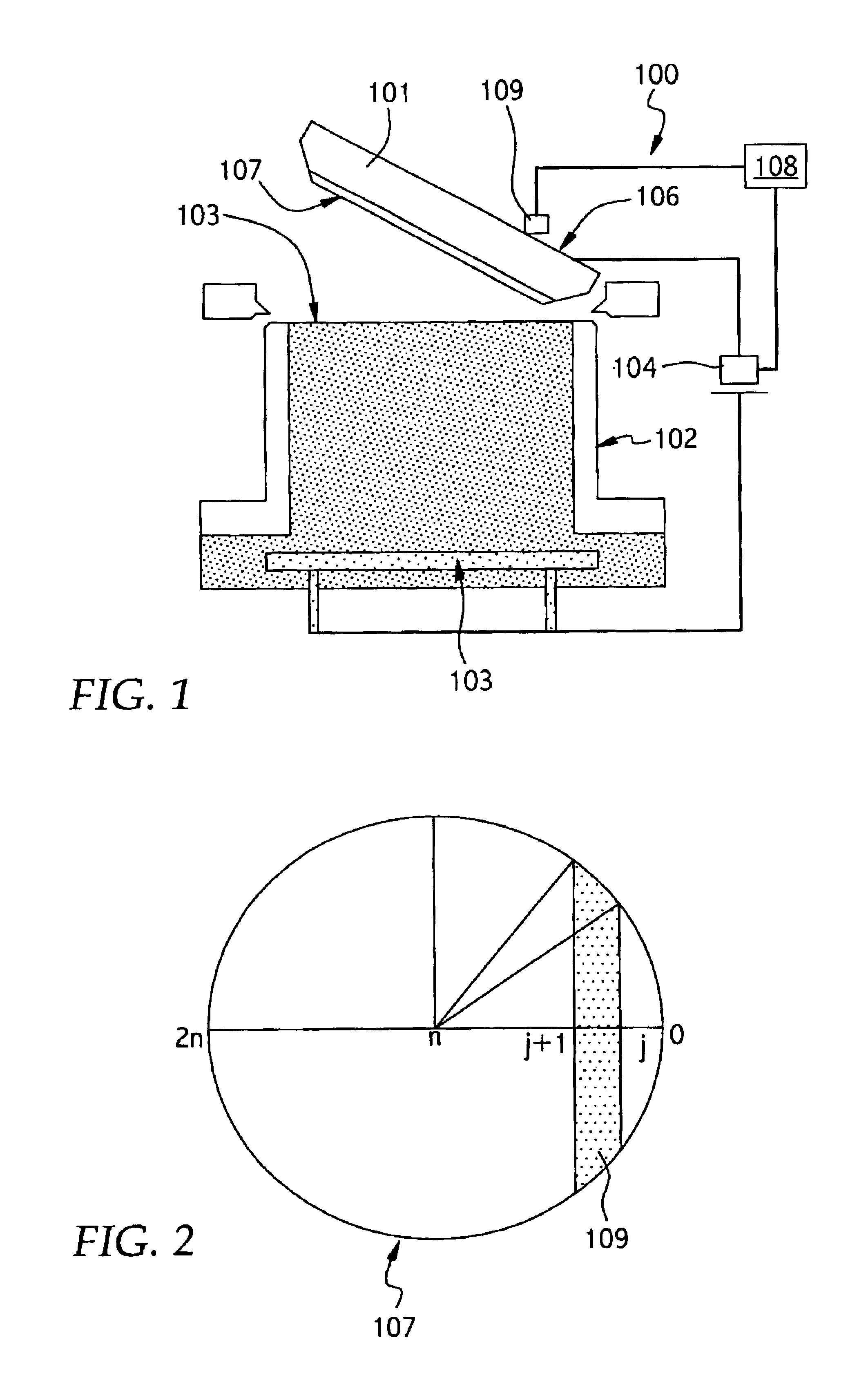
[0018]FIG. 1 illustrates a plating cell 100 during a substrate immersion process of the invention. Plating cell 100 generally includes a cell body 102 configured to contain a fluid solution and an anode 105 therein. The cell body 102 generally includes an open top portion configured to receive a lid 101 therein. Lid 101 can generally be configured to support a substrate 107...


PUM

PropertyMeasurementUnit
Timeaaaaaaaaaa
Poweraaaaaaaaaa
Densityaaaaaaaaaa

Abstract

A method and apparatus for providing a uniform current density across an immersed surface of a substrate during an immersion process. The method includes the steps of determining a time varying area of an immersed portion of the substrate during the immersion process, and supplying a time varying current to the substrate during the immersion process, wherein the time varying current is proportional to the time varying area and is configured to provide a constant current density to the immersed portion of the substrate.

Description

BACKGROUND OF THE INVENTION[0001]1. Field of the Invention[0002]Embodiments of the invention generally relate to systems for immersing a substrate in an electrolyte solution, and more particularly, to apparatuses and methods for controlling electrical power applied to a substrate during an immersion process.[0003]2. Description of the Related Art[0004]Metallization of sub-quarter micron sized features is a foundational technology for present and future generations of integrated circuit manufacturing processes. More particularly, in devices such as ultra large scale integration-type devices, i.e., devices having integrated circuits with more than a million logic gates, the multilevel interconnects that lie at the heart of these devices are generally formed by filling high aspect ratio interconnect features with a conductive material, such as copper or aluminum, for example. Conventionally, deposition techniques such as chemical vapor deposition (CVD) and physical vapor deposition (PV...

Claims


Application Information

Patent Timeline
IPC IPC(8): C25D7/12H01L21/288H01L21/02H01L21/70H01L21/768C25D21/12
CPCH01L21/2885C25D17/001C25D7/123H01L21/76877C25D21/12
Inventor ZHENG, BOBAJAJ, RAJEEVWANG, ZHONGHUI ALEX
Owner APPLIED MATERIALS INC
Why Eureka
Try Eureka