Casing unit for circuit assembly and method for producing the circuit assembly

a technology for circuit assembly and casing unit, which is applied in the direction of electrical apparatus casing/cabinet/drawer details, coupling device connections, casings/cabinets/drawers, etc., can solve the problems of difficult assembly and deformation of the casing body, and achieve the effect of waterproofing the power circuit section surely and easily

Inactive Publication Date: 2005-06-28
SUMITOMO WIRING SYST LTD
View PDF9 Cites 28 Cited by
  • Summary
  • Abstract
  • Description
  • Claims
  • Application Information

AI Technical Summary

Benefits of technology

[0012]According to the above casing unit, at least a part of the power circuit section is covered with and protected by the casing body. It is possible to enhance adherence (to enhance a close contact) between the power circuit section and the circuit arrangement surface of the heat radiation member by pressing the power circuit section on the circuit arrangement surface through the opening in the casing body. The opening facilitates inspection of the power circuit section. Because the shape retention member interconnects the periphery around the opening at a plurality of positions across the opening, it is possible to prevent the casing unit from being deformed due to a shrinkage cavity in spite of the large opening.
[0013]The casing unit can be used as the casing body for the circuit assembly, as it is. However, if the shape retention member is removed at a suitable time after forming and cooling, pressing and inspecting works of the power circuit section will be easier.
[0014]In the case where the breakable reduced portion is provided on a boundary area or an adjacent area between the shape retention member, and where the peripheral edge of the opening and a cross section of the breakable reduced portion is smaller than that of a member body of the shape retention member, it is possible to cut off the shape retention member from the casing unit more easily by utilizing the reduced breakable portion.
[0015]A structure of the casing unit of the embodiments of the present invention is not limited. For example, so long as a plurality of connector housings are integrally provided on the peripheral edge around the opening in the casing body to interconnect the power circuit section and an external circuit to each other, and the opening is formed at an inside of the connector housing, the casing unit will be any structure. While interconnecting the power circuit section and the external circuit to each other by utilizing the respective connector housings, the opening is disposed at the inside of the connector housings arranged on the periphery of the casing body and the large opening can be obtained while keeping a compact structure. Because the connector housing increases a thickness of the casing body, which prevents the shrinkage cavity upon cooling after forming, the shape retention member will further prevent the shrinkage cavity significantly.
[0017]According to the method, it is possible to suppress deformation of the casing unit from a shrinkage cavity after forming. This deformation suppression is achieved by the shape retention member without using a special tool, while achieving a mass-production by a common forming method in which a heated molten synthetic resin is poured into a mold. It is possible to perform a work through the opening (a work of pressing the power circuit section and an inspection work) smoothly by cutting off the shape retention member from the casing unit after cooling.
[0020]In this method, a liquid waterproof resin is poured through the opening into the casing body after finishing the second step of adhering, and the waterproof resin is solidified to form a waterproof layer for sealing the power circuit section. It is possible to waterproof the power circuit section surely and easily. It is also possible to confirm a pouring state of the waterproof resin through the opening.

Problems solved by technology

However, if a large opening is provided in the casing body, the casing body might be deformed because of a shrinkage cavity caused upon cooling after forming.
There is a possibility of encountering a difficult assembling in the worst case.

Method used


Image

  • Casing unit for circuit assembly and method for producing the circuit assembly
  • Casing unit for circuit assembly and method for producing the circuit assembly
  • Casing unit for circuit assembly and method for producing the circuit assembly

Examples


Embodiment Construction

[0029]In describing the exemplary embodiments of the present invention, reference will be made herein to FIGS. 1 to 6 of the drawings in which like numerals refer to like features of the invention. Features of the invention are not necessarily shown to scale in the drawings.

[0030]Referring now to the drawings, embodiments of a casing unit for a circuit assembly and a method for producing the circuit assembly in accordance with the present invention will be described below. An example in which the present invention is applied to a circuit assembly is described here. The circuit assembly distributes an electrical power supplied from a common power source on a vehicle or the like to a plurality of electrical loads.

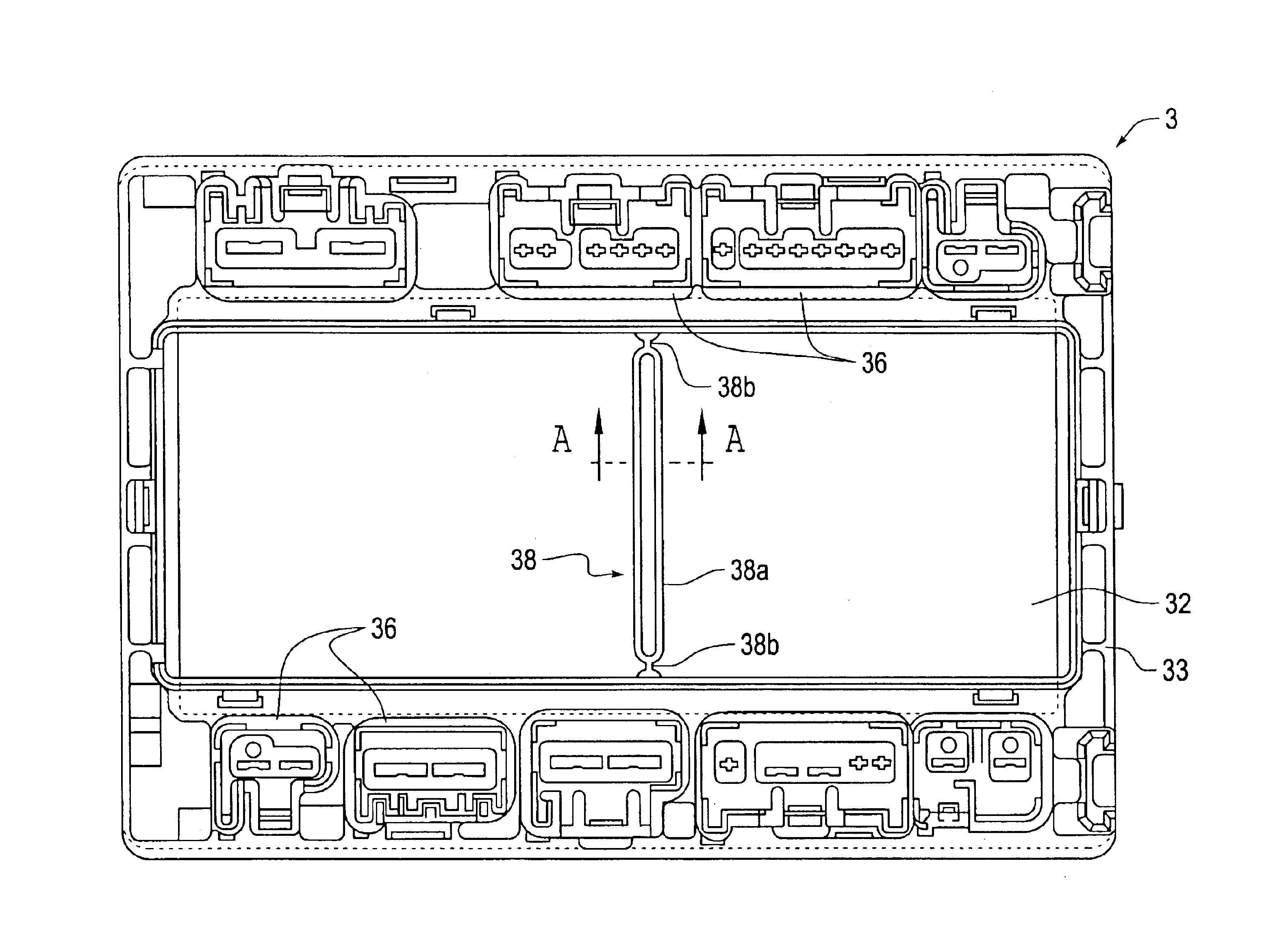
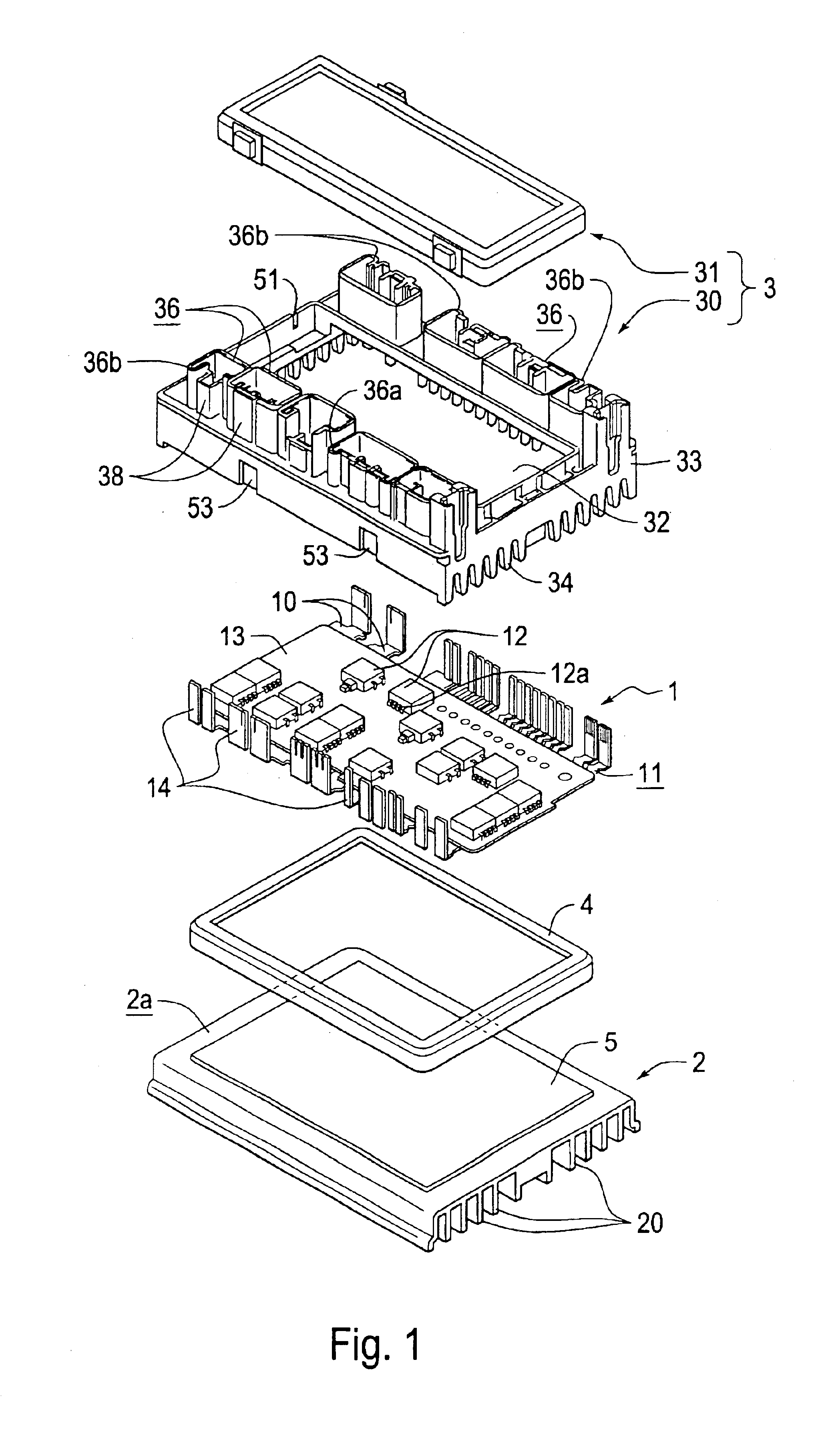
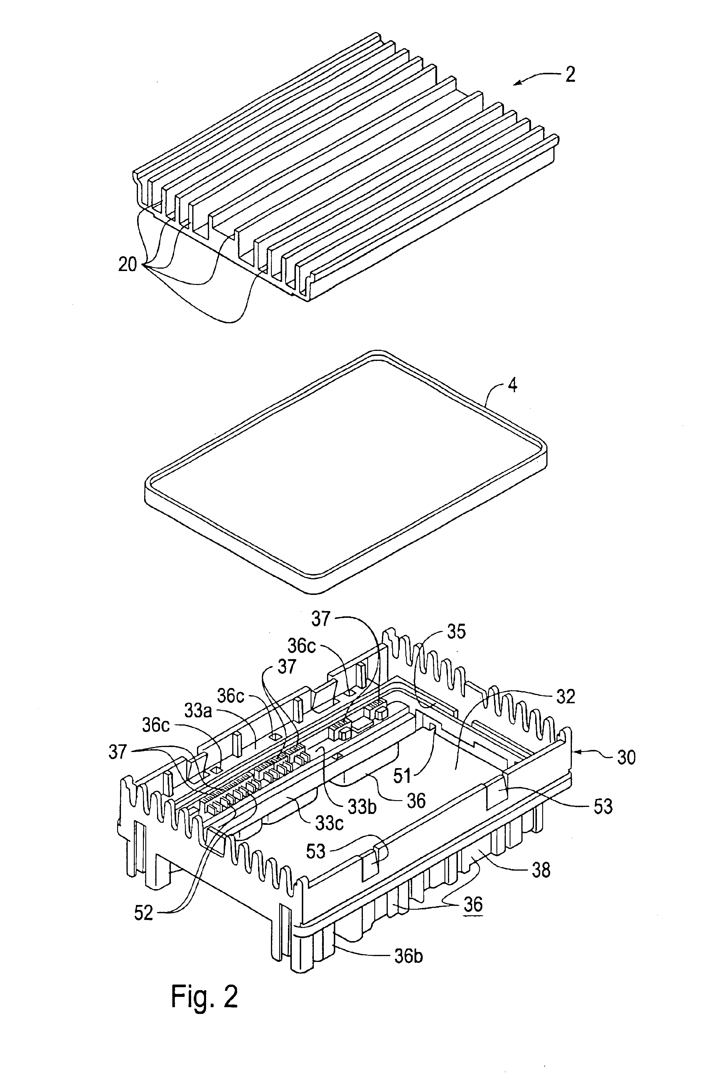
[0031]FIG. 1 is an exploded perspective view of an embodiment of a circuit assembly in accordance with the present invention. The circuit assembly comprises a power circuit section 1 including a plurality of bus bars 10, a heat radiation member 2 on which the power circuit se...


PUM


Abstract

A power circuit section is adhered to a circuit arrangement surface on a heat radiation member to form a circuit assembly. A casing body is mounted on the heat radiation member. The casing body is provided with an opening that exposes at least the upper portion of the power circuit section. A shape retention member is disposed across the opening for interconnecting a peripheral edge of the opening to each other at a plurality of positions. A casing unit is made of a synthetic resin. The shape retention member suppresses a deformation of the casing body due to a shrinkage cavity. After cooling the casing unit, the shape retention member is removed to define a large opening, if desired.

Description

CLAIM FOR PRIORITY[0001]The present invention claims priority to Japanese Patent Application JP-A2003-036467 filed Feb. 14, 2003.BACKGROUND OF THE INVENTION[0002]1. Field of Invention[0003]This invention relates to a casing unit for a circuit assembly that can be used as a power distributor on a vehicle for distributing an electrical power to a plurality of electronic units from a common power source on a vehicle, and also relates to a method for producing the circuit assembly.[0004]2. Description of Related Art[0005]Heretofore, as means for distributing an electrical power to each electronic unit from a common power source on a vehicle, a junction box has been known which constitutes a power circuit section in which a plurality of bus bar boards are laminated and a fuse and a relay switch are incorporated on the boards.[0006]Recently, in order to downsize a junction box for distributing an electrical power to each electronic unit and to realize a high speed switching control, a cir...

Claims


Application Information

Patent Timeline
Patent Type & Authority Patents(United States)
IPC IPC(8): H05K7/02H01R13/518H05K5/00H05K5/02H05K7/20
CPCH05K7/026Y10S248/906
Inventor ONIZUKA, TAKAHIROYAMAGUCHI, JUN
Owner SUMITOMO WIRING SYST LTD
Why Eureka
Try Eureka