Cooling fan for microwave oven

a technology for cooling fans and microwave ovens, applied in the field of cooling fans, can solve the problems of considerable air suction noise, noise level of 43.1 db[a], etc., and achieve the effect of improving the cooling efficiency

Inactive Publication Date: 2005-06-28
LG ELECTRONICS INC
View PDF3 Cites 6 Cited by
  • Summary
  • Abstract
  • Description
  • Claims
  • Application Information

AI Technical Summary

Benefits of technology

[0016]Accordingly, the present invention has been made in an effort to solve the problems occurring in the related art, and an object of the present invention is to provide a cooling fan for a microwave oven, which is adapted for directing axially sucked airflow to be evenly distributed over a magnetron and a high voltage transformer, thereby improving a cooling efficiency.

Problems solved by technology

However, the conventional microwave oven constructed as mentioned above suffers from defects in that, since the magnetron 12 and high voltage transformer 14 are disposed up and down in the electric device chamber and the axial flow fan 20 is arranged behind them, a some portion of the airflow discharged at a high velocity from the axial flow fan 20 simply passes through a space which is defined between a lower end of the magnetron 12 and an upper end of the high voltage transformer 14.
Nevertheless, the conventional axial flow fan 20 configured as described above has disadvantages in that, when the axial flow fan 20 is driven by the motor 16 to be rotated at 2856 RPM, a volume flow rate sucked into the cabinet 2 is 1.73 CMM, and under this condition, a noise level reaches 43.1 dB[A], whereby considerable air suction noise is generated during rotation of the blades 24.

Method used


Image

  • Cooling fan for microwave oven
  • Cooling fan for microwave oven
  • Cooling fan for microwave oven

Examples


Embodiment Construction

[0034]Reference will now be made in greater detail to a preferred embodiment of the invention, an example of which is illustrated in the accompanying drawings. Wherever possible, the same reference numerals will be used throughout the drawings and the description to refer to the same or like parts.

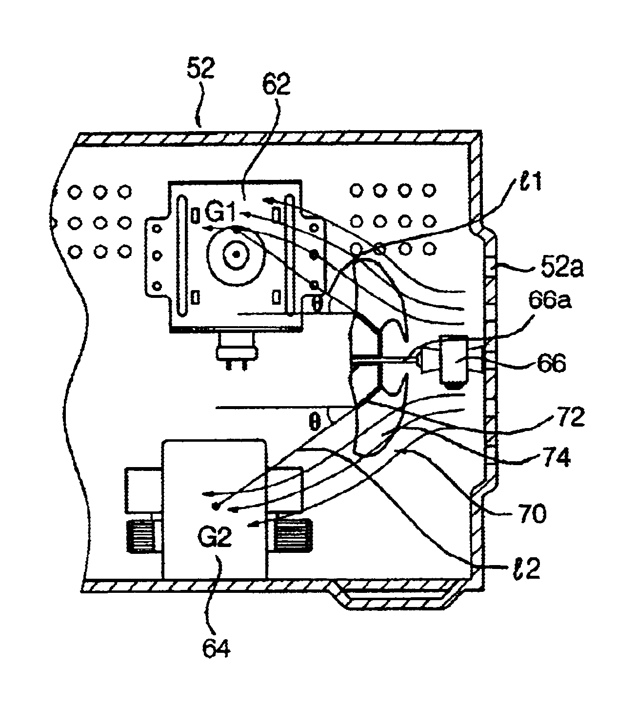
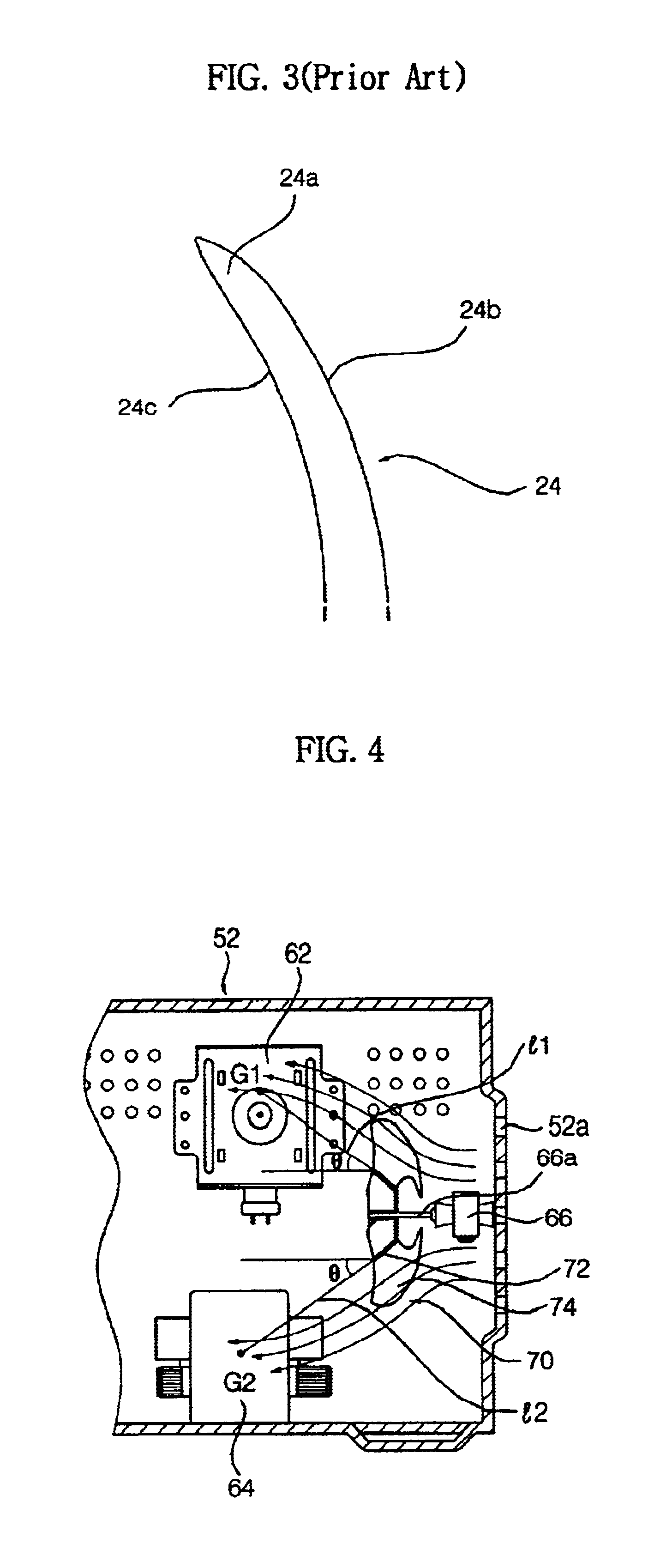
[0035]FIG. 4 is a side cross-sectional view illustrating a state wherein a cooling fan in accordance with a first embodiment of the present invention is disposed in a electric device chamber of a microwave oven, and FIG. 5 is a perspective view independently illustrating the cooling fan according to the first embodiment of the present invention.

[0036]As shown in FIG. 4, in the electric device chamber of the microwave oven, there are disposed up and down a magnetron 62 for radiating high frequency waves into a cooking chamber (not shown) defined in a cabinet 52 and a high voltage transformer 64 for applying a high voltage to the magnetron 62. A mixed flow fan 70 is arranged behind the magne...


PUM


Abstract

Disclosed is a cooling fan for a microwave oven, adapted for directing axially sucked airflow to be evenly distributed over a magnetron and a high voltage transformer. The cooling fan comprises a mixed flow fan having a specified hub angle, or an axial flow fan having optimized design parameters such as a ratio of an outer diameter of the fan to a width of a electric device chamber defined in a cabinet, a hub ratio, a sweep angle, a pitch angle, a maximum camber rate, etc.

Description

BACKGROUND OF THE INVENTION[0001]1. Field of the Invention[0002]The present invention relates to a cooling fan for cooling a magnetron and a high voltage transformer disposed in a electric device chamber of a microwave oven, and more particularly, the present invention relates to a cooling fan for a microwave oven, which comprises a mixed flow fan having a specified hub angle, or an axial flow fan having optimized design parameters such as a ratio of an outer diameter of the fan to a width of a electric device chamber defined in a cabinet, a hub ratio, a sweep angle, a pitch angle, a maximum camber rate, etc.[0003]2. Description of the Related Art[0004]Generally, a microwave oven serves as an electric home appliance which is operated to induce increased molecular motion of water contained in a food item using high-frequency electromagnetic waves, cause molecules of water to vibrate, and generate heat within the food item to thereby cook the food item in a short period of time.[0005]...

Claims


Application Information

Patent Timeline
Patent Type & Authority Patents(United States)
IPC IPC(8): F04D29/38H05B6/80
CPCH05B6/642F04D29/384
Inventor SHON, SANG BUM
Owner LG ELECTRONICS INC
Why Eureka
Try Eureka