Method of measuring ion beam angles

Inactive Publication Date: 2005-06-28
VARIAN SEMICON EQUIP ASSOC INC
View PDF7 Cites 12 Cited by
  • Summary
  • Abstract
  • Description
  • Claims
  • Application Information

AI Technical Summary

Benefits of technology

[0006]The invention provides a method of determining beam twist and/or calibrating tilt angles of an ion beam of an ion beam implanter relative to a first channel in a crystalline target. The inventive method can be used to calibrate the machine to an accuracy which is comparable to the precision of variance of such angle. In one aspect the inventive method comprises the steps of: a) providing reference data defining a known relationship between the beam tilt and twist angles and beam channeling in at least one preselected second channel of said crystalline target,

Problems solved by technology

Further, it is sometimes desirable to provide beam incidence angles other than perpendicular to the substrate plane for reasons related to the geometry of the device being manufactured.
There is no guarantee that the ion beam, an energetic entity sensitive to magnetic and electric fields, bears any fixed angular relationship to any mechanical hardware.
While this method provides a real time method of angular measurement of wafer chuck directly to the ion beam (as opposed to the waveguide or other hardware), its use will be limited to regimes dictated by its accuracy.

Method used


Image

  • Method of measuring ion beam angles
  • Method of measuring ion beam angles
  • Method of measuring ion beam angles

Examples


Embodiment Construction

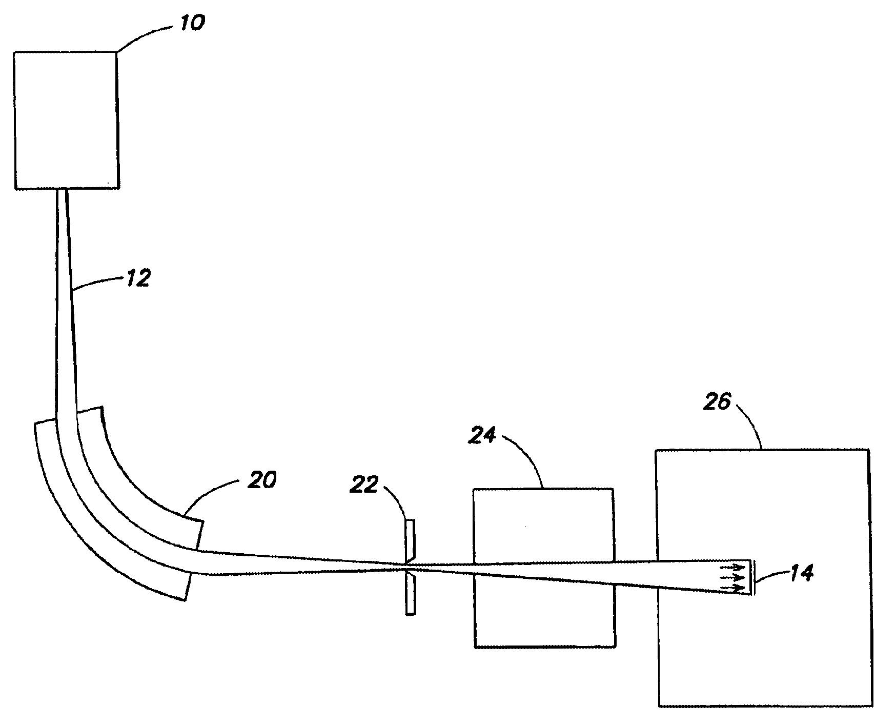
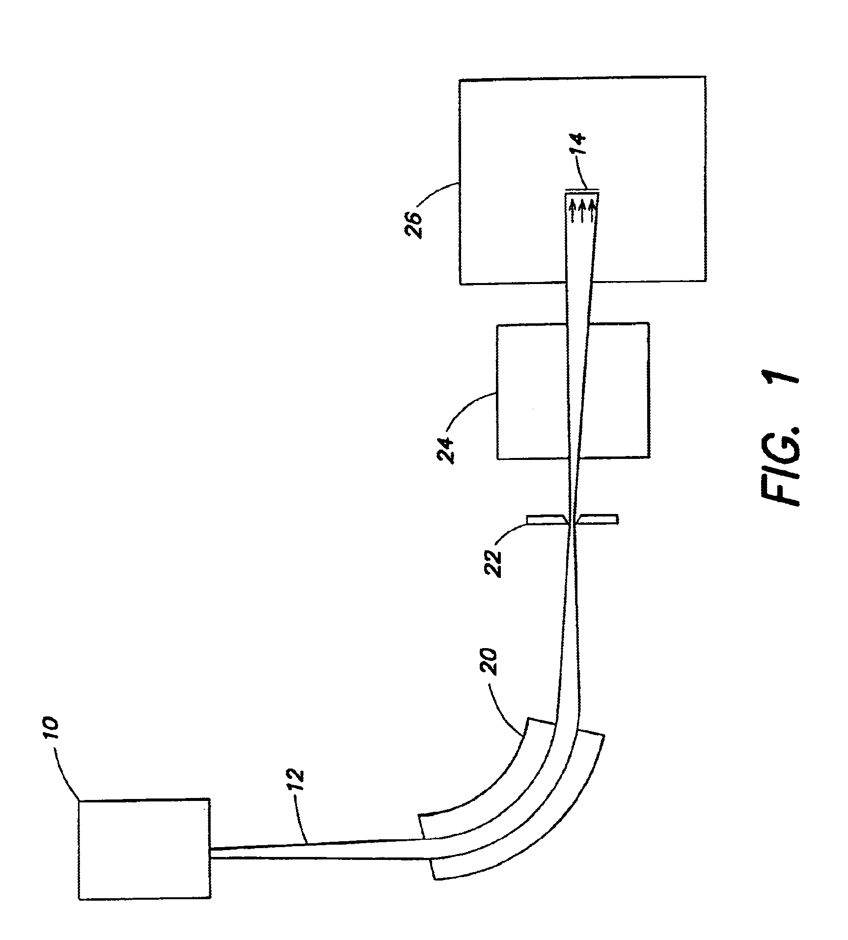
[0017]A schematic block diagram of a typical ion implanter device is shown in FIG. 1. An ion source 10 directs an ion beam 12 along a beam path toward a target 14, typically a semiconductor wafer. The ion beam 12 is deflected and focused by a mass analyzing magnet 20. The ion beam is focused in the plane of a mass resolving slit assembly 22. A variety of slit assembly configurations are known, including the rotating cylinder configuration of U.S. Pat. No. 5,629,528 and the prior slit assembly configurations described in the background thereof The ion beam 12 is accelerated to a desired energy by an accelerator 24 and impinges on the target 14 located within a target chamber 26. The entire region between the ion source 10 and the target 14 is evacuated during ion implantation.

[0018]The ion beam 12 may be distributed over the surface of target 14 by mechanically scanning target 14 with respect to the beam, by scanning the ion beam with respect to the target or by a combination of beam...


PUM


Abstract

A method of determining beam twist and / or calibrating tilt angles of an ion beam of an ion beam implanter relative to a first channel of a crystalline target. The method can be used to calibrate the machine to an accuracy which is comparable to the precision of variance of such angle. The method includes the steps of a) providing reference data defining a known relationship between the beam tilt and twist angles and beam channeling in at least one preselected second channel of the crystalline target, at least some of the data providing first and second reference tilt angles at which channeling occurs for a given twist angle, the first and second tilt angles being different, b) without varying the twist angle, measuring channeling severity around a range of estimated tilt angles surrounding each of said first and second reference tilt angles and determining from the measurements a point of maximum channeling severity within each range; and c) comparing the determined points to the reference data to determine the twist angle and / or calibrate the tilt angle.

Description

FIELD OF THE INVENTION[0001]The invention pertains to a method of measuring the incidence angle of an ion beam on a semiconductor wafer in an ion implanter, and the use of this method to precisely calibrate the incidence angle. In particular both tilt and twist angles are determined by the inventive method.BACKGROUND OF THE INVENTION[0002]In the manufacture of semiconductor devices using ion implantation, it is desirable to control the beam incidence angle, because the implantation depth is a function of the beam incidence angle as a result of the well-known channeling effect. Further, it is sometimes desirable to provide beam incidence angles other than perpendicular to the substrate plane for reasons related to the geometry of the device being manufactured. A description of ion implantation techniques utilizing tilted implantation steps can be found in U.S. Pat. No. 5,696,382 issued Dec. 9, 1997 to Kwang, and U.S. Pat. No. 5,909,622 issued Jun. 1, 1999 to Kadosh et al. As device g...

Claims


Application Information

Patent Timeline
IPC IPC(8): H01J37/30H01J37/304H01J37/317
CPCH01J37/304H01J37/3171H01J2237/30433H01J2237/24528
Inventor LARSEN, GRANT KENJI
Owner VARIAN SEMICON EQUIP ASSOC INC
Why Eureka
Try Eureka