Diesel engine lubricating oil contaminant sensor method

a technology of lubricating oil and sensor method, which is applied in the direction of machines/engines, pulse techniques, instruments, etc., can solve the problem that the change in the dielectric constant of oil (permittivity) is a relatively unreliable predictor of oil quality

Inactive Publication Date: 2005-06-28
DELPHI TECH INC
View PDF17 Cites 60 Cited by
  • Summary
  • Abstract
  • Description
  • Claims
  • Application Information

AI Technical Summary

Benefits of technology

[0009]The change in the dielectric constant of the oil (permittivity) is a relatively unreliable predictor of oil quality, because permittivity is greatly affected by presence of polar molecules, such as antifreeze, water and many of the additives that ...

Problems solved by technology

The change in the dielectric constant of the oil (permittivity) is a relatively unreliable predictor of oil quality, because permittivity i...

Method used


Image

  • Diesel engine lubricating oil contaminant sensor method
  • Diesel engine lubricating oil contaminant sensor method
  • Diesel engine lubricating oil contaminant sensor method

Examples


Embodiment Construction

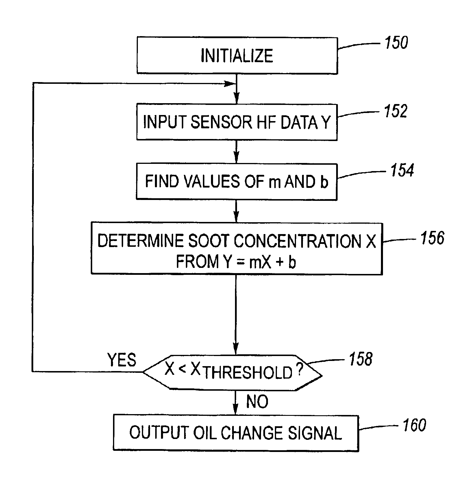
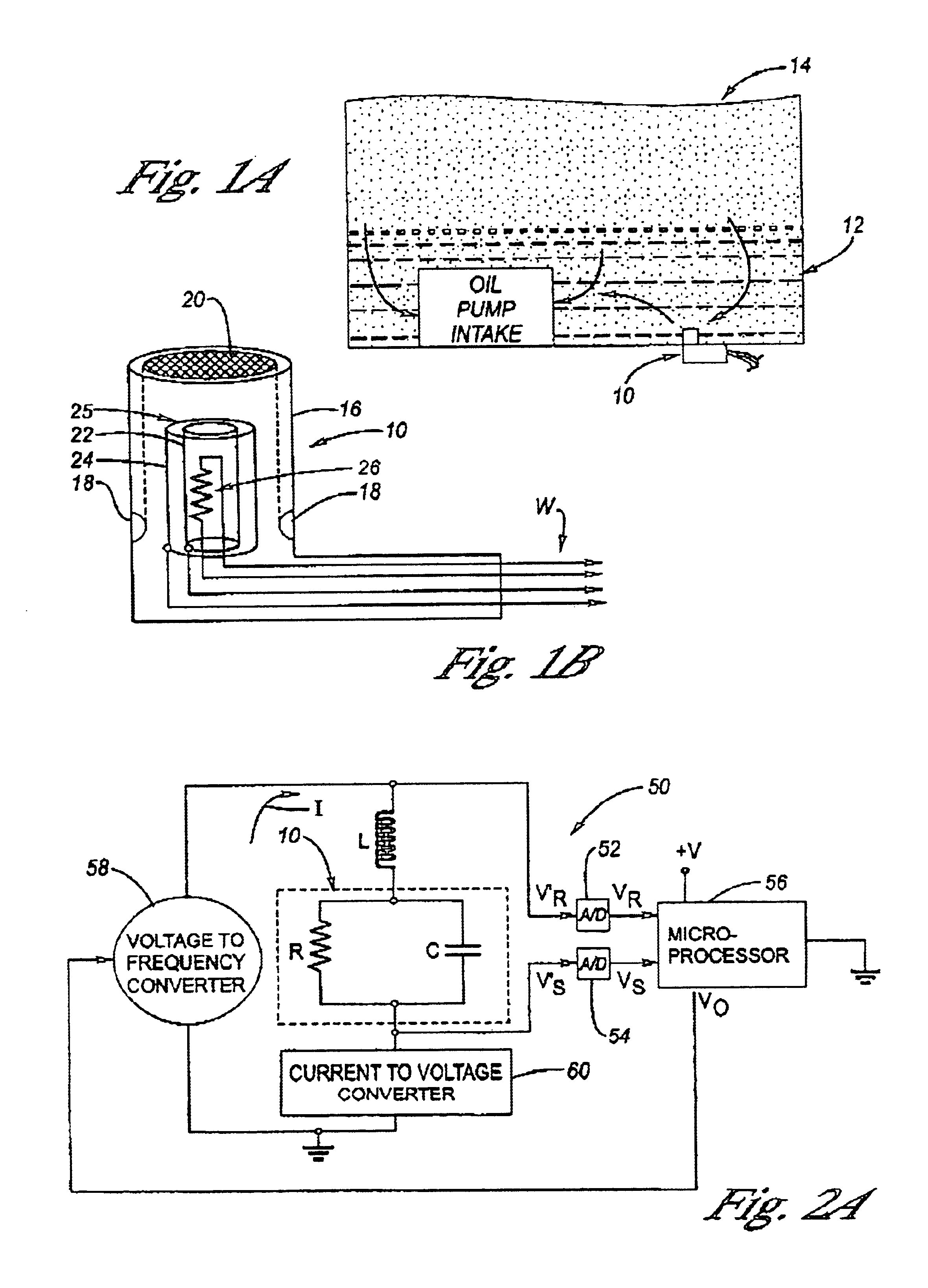
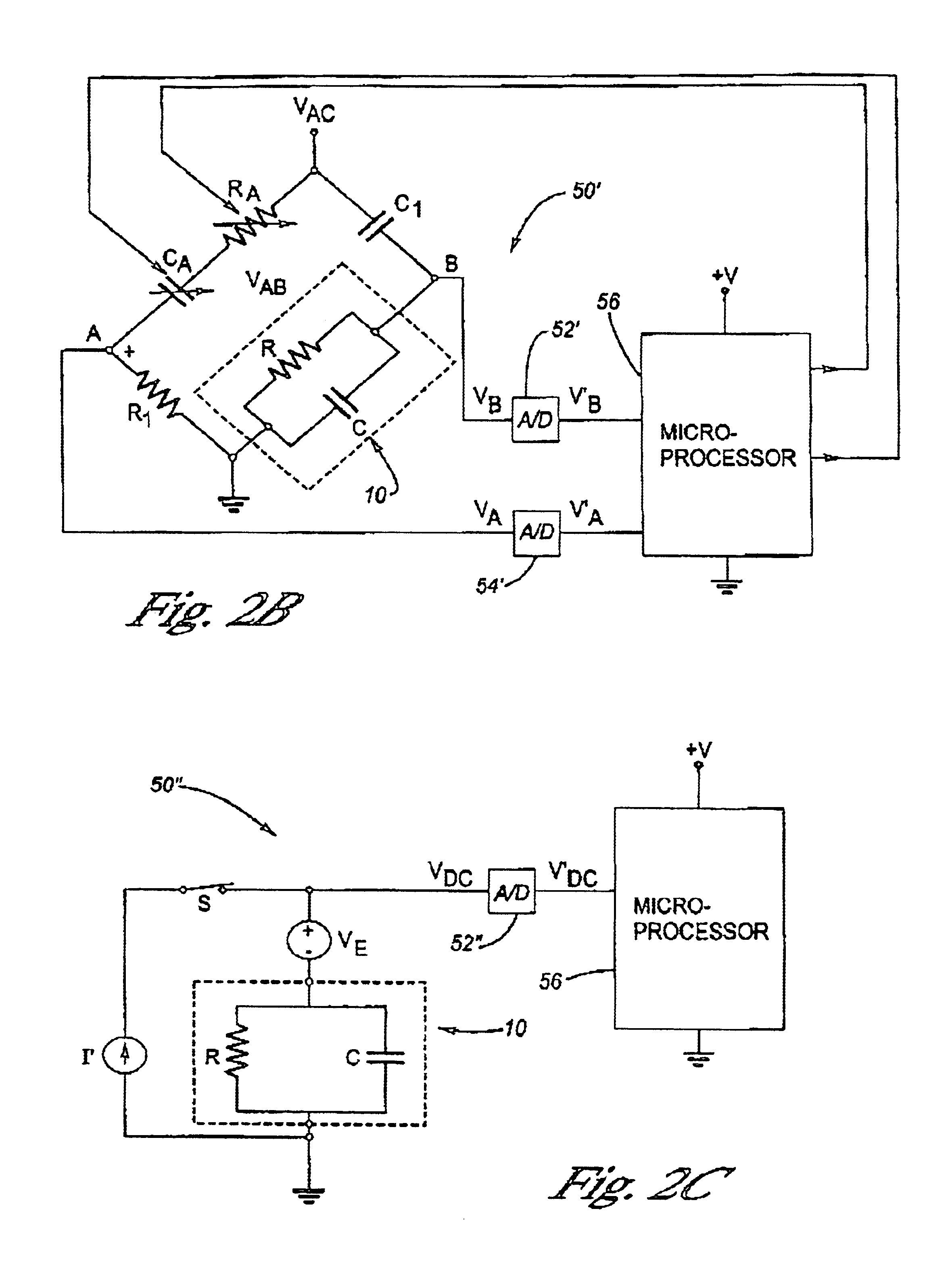
[0044]Referring now to the Drawing, FIGS. 1A through 2C and 27 and 28 depict an example of apparatus to carryout the Diesel engine oil contaminant sensor method according to the present invention; and FIGS. 3 through 26 depict various graphical plots which support carrying out the various steps of the Diesel engine oil contaminant sensor method according to the present invention.

[0045]FIG. 1A depicts an environment of placement and operation of an oil sensor 10 at the bottom of an oil pan 12 of a Diesel engine 14. As shown at FIG. 1B, the oil sensor 10 has a cylindrical shell 16 having apertures 18 and an open top end 20. Inside the shell 16 is a pair of concentrically arranged and mutually separated cylindrical capacitor plates 22, 24 which collectively form a capacitor 25, each of which being connected to a respective portion of wiring, W. Depending on the method used according to the present invention, a thermometric sensor 26, as for example a thermistor, is placed within the sh...


PUM


Abstract

A method by which contaminant (soot) content in Diesel engine oil is determined using electrical conductivity measurements of the Diesel oil at a high frequency, or by which contaminant (soot and/or water and/or anitfreeze) content is determined using the ratio of electrical conductivity measurements of the Diesel oil at a high frequency to the electrical conductivity measurements of the Diesel oil at a low frequency. Both the conductivity ratio and the high frequency conductivity are essentially independent of the brand of oil. High frequency is defined to be above 2 MHz whereas low frequency is defined to be D.C. to about 1 kHz.

Description

TECHNICAL FIELD[0001]The present invention relates generally to Diesel engine oil contaminant sensors and more specifically to a method that measures the electrical conductivity of the lubricating oil to determine the amount of at least one of soot, water and antifreeze therein.BACKGROUND OF THE INVENTION[0002]Lubricating oil used in gasoline engines for lubrication of moving components, hereinafter simply referred to as “oil”, deteriorates by the depletion of the additives and the increase in the acidity of the oil, as measured by a quantity called the total acid number (TAN). Oil in Diesel engines is degraded by the same mechanisms as in gasoline engines, but with the additional presence of soot particles, which increases as the oil ages. During usage of a Diesel engine, the crankcase oil gradually builds up soot which is a combustion product in the combustion chamber of the engine and which is transferred in small amounts to the crankcase oil. When the soot builds up to an unacce...

Claims


Application Information

Patent Timeline
IPC IPC(8): G01N27/06G01N33/28G01N33/26
CPCG01N33/2888G01N27/06
Inventor HEREMANS, JOSEPH PIERREWANG, SU-CHEE SIMONSCHROEDER, THADDEUSNAGY, LOUIS L.
Owner DELPHI TECH INC
Why Eureka
Try Eureka