Low pressure drop coated diesel exhaust filter

a technology of diesel exhaust and low pressure drop, which is applied in the direction of machines/engines, physical/chemical process catalysts, separation processes, etc., can solve the problems of inconvenient exhaust system pressure drop, undetected large pressure drop, and more complete obstruction, so as to promote nitrogen oxide reduction and/or carbon compound, reduce or avoid obstruction, and reduce nitrogen oxide and unburned carbon compound emissions

Inactive Publication Date: 2007-06-21
CORNING INC
View PDF13 Cites 70 Cited by
  • Summary
  • Abstract
  • Description
  • Claims
  • Application Information

AI Technical Summary

Benefits of technology

[0009] In a specific embodiment, at least 60% of the catalyst is distributed from a mid-point of the thickness of the walls to the outlet surfaces of the walls. The inlet surfaces of the ceramic walls are substantially free of the catalyst to prevent the catalyst from obstructing the flow of exhaust gases through the walls. However, a sufficient amount of catalyst is distributed between a mid-point in the thickness of the walls and the outlet channel surfaces to promote nitrogen oxide reduction and / or carbon compound (carbon monoxide, hydrocarbon) oxidation. Finally, embodiments wherein the increase in concentration of the catalyst is substantially non-linear along the thickness of the ceramic wall, and / or wherein the outlet wall surfaces of the filter structure remain substantially free of bulk catalyst coating, are provided. The absence of catalysts deposited on the surfaces of the porous channel walls of the structure is helpful to reduce or avoid the obstruction of exhaust gas flow through the walls.
[0010] The coated diesel exhaust filter of the invention provides a filter that is capable of reducing nitrogen oxide and unburned carbon compound emissions while filtering soot from the engine exhaust gases, and maintains a relatively low pressure drop even when soot accumulates on the inlet surfaces of the ceramic walls. It is also relatively easy and simple to manufacture from conventional materials.

Problems solved by technology

While such prior art coated diesel exhaust filters are reasonably effective in achieving their purposes, the inventors have observed that the pressure drop they apply to the exhaust system becomes disadvantageously large after soot deposits begin to accumulate in the inlet surfaces of the ceramic walls.
The applicants believe that this undesirably large pressure drop is caused by a partial obstruction of the micro-structure of the ceramic walls from the particles of catalysts that are deposited therein as a result of the coating process, which in turn promotes a more complete obstruction as soot begins to fill the unobstructed pores.

Method used


Image

  • Low pressure drop coated diesel exhaust filter
  • Low pressure drop coated diesel exhaust filter

Examples


example

[0019] Several ceramic honeycomb catalyst substrate samples are blown out with high pressure air to remove dust prior to processing. The samples selected are of aluminum titanate composition with principal crystal phases of aluminum titanate and alkaline earth feldspar. The honeycombs have a channel density of about 46 cells / cm2, a channel wall thickness of about 0.3 mm, and a wall porosity of about 50% by volume with high gas permeability. The honeycombs have an average linear coefficient of thermal expansion (CTE) of approximately 8×10⁻⁷ / ° C. as measured at a temperature of about 1000° C.

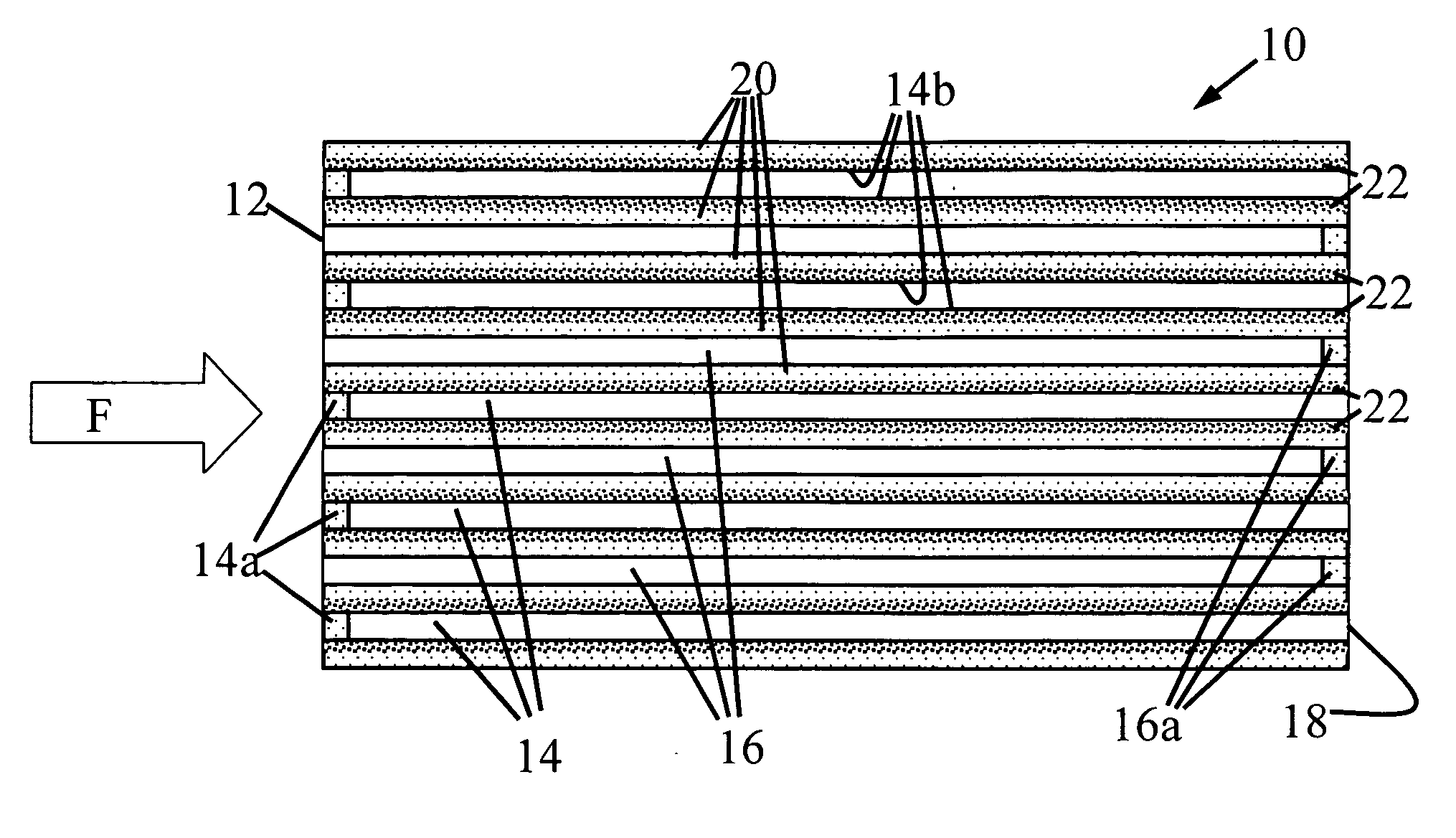
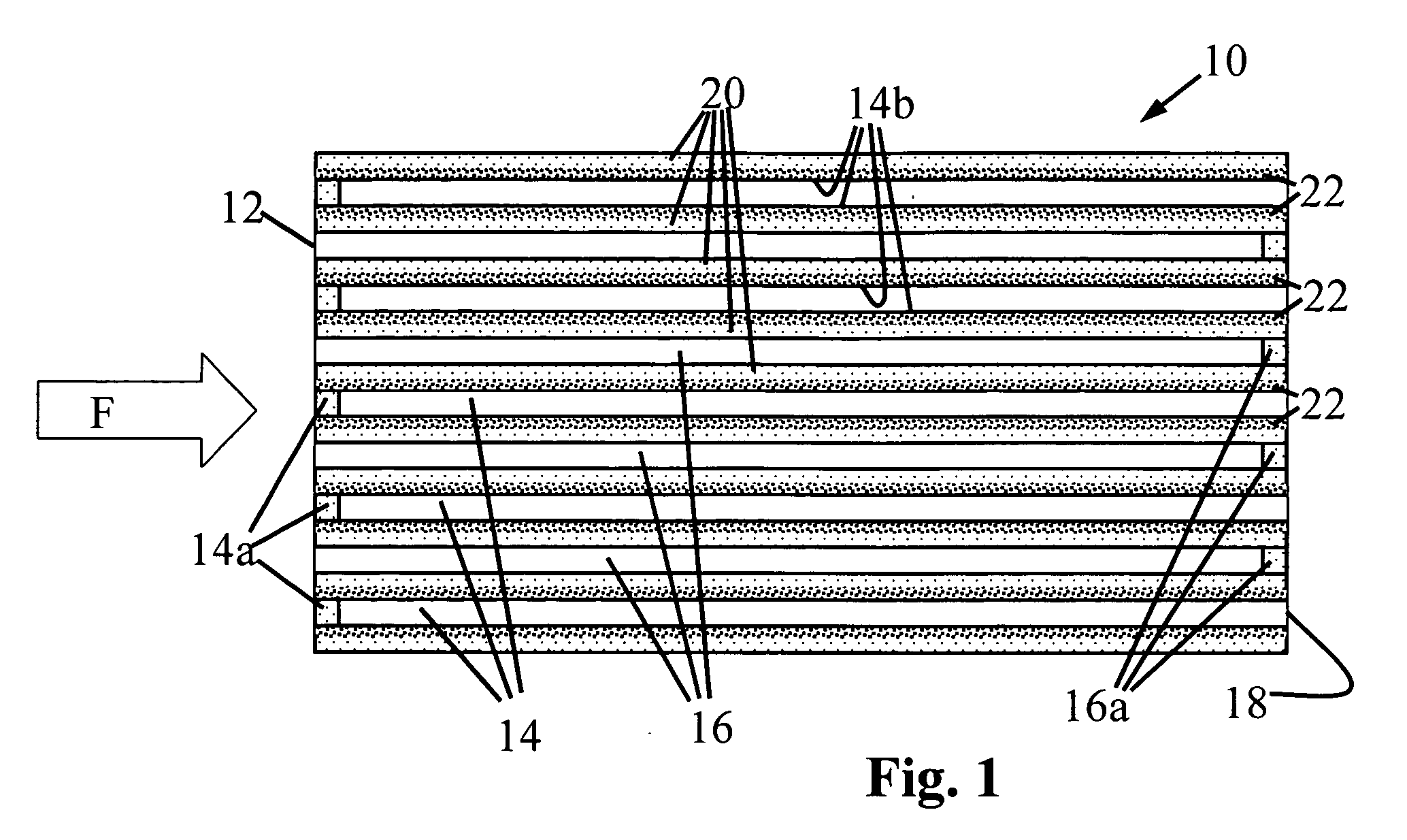
[0020] Opposing ends of these honeycombs are selectively plugged to form a wall flow filter body with inlet channels plugged at the filter outlet end and outlet channels plugged at the filter inlet end. Half of the channels are plugged in an alternating checkerboard pattern at the inlet end of the honeycomb to form the filter outlet channels, and the remaining channels are plugged at the opposite...


PUM

PropertyMeasurementUnit
Porosityaaaaaaaaaa
pore sizeaaaaaaaaaa
pore sizeaaaaaaaaaa

Abstract

A coated diesel exhaust filter is provided that applies a relatively low pressure drop across the exhaust system despite the buildup of soot deposits. The filter includes a porous ceramic structure having an inlet end, an outlet end, and a plurality of gas inlet and gas outlet channels disposed between the inlet and outlet ends, the channels being separated by porous ceramic walls. A catalyst is distributed at least partly within the porous ceramic walls of the structure, and is distributed at a higher concentration within portions of the ceramic walls adjacent to the outlet surfaces than within portions of the ceramic walls adjacent the inlet surfaces. Both the inlet and outlet surfaces are substantially free of the catalyst in order to maintain a gas-conducting porosity in these surfaces. The resulting filter effectively treats nitrogen oxides, carbon monoxide and unburned hydrocarbons present in the exhaust gas stream while advantageously imposing a relatively low pressure drop across the exhaust system even when soot deposits accumulate on the inlet surfaces of the ceramic walls.

Description

[0001] This application claims the benefit of U.S. Provisional No. 60 / 751,062, filed Dec. 16, 2005, entitled “Low Pressure Drop Coated Diesel Exhaust Filter.”FIELD OF THE INVENTION [0002] The present invention is in the field of combustion engine exhaust emissions control and particularly relates to ceramic wall flow filters used to trap particulates such as soot that are normally present in the exhaust streams of diesel engines. BACKGROUND OF THE INVENTION [0003] Catalyst-coated diesel exhaust filters are well-known in the prior art. Such filters generally comprise a honeycomb structure of a porous ceramic material, such as silicon carbide (SiC). Such filters have an inlet end for receiving diesel exhaust gas, an outlet end, and a plurality of gas inlet and gas outlet channels disposed between the inlet and outlet ends which are separated by porous ceramic walls. Exhaust gases conducted through the inlet end of the honeycomb structure must pass through the porous ceramic walls befo...

Claims


Application Information

Patent Timeline
Patent Type & Authority Applications(United States)
IPC IPC(8): B01D50/00
CPCB01D53/944B01J35/0006B01J35/04B01J37/0201B01J37/0215F01N3/0222F01N3/035F01N2330/06F01N2330/30F01N2510/0682Y02A50/20
Inventor BEALL, DOUGLAS MUNROEHEIBEL, ACHIM KARL-ERICHTAO, TINGHONG
Owner CORNING INC
Why Eureka
Try Eureka