Color image forming apparatus using registration marks

a color image and registration mark technology, applied in the field of color image forming apparatus, can solve the problems of inability to detect the edge of the color registration mark with a good reproducibility, difficulty in ensuring the signal difference between the toner surface and the substrate surface, and inability to achieve good reproducibility. the effect of good accuracy

Active Publication Date: 2005-06-28
KONICA CORP
View PDF1 Cites 41 Cited by
  • Summary
  • Abstract
  • Description
  • Claims
  • Application Information

AI Technical Summary

Benefits of technology

[0014]Thus, this invention has solved the above-mentioned problems (1) and (2); its first object is to provide an image forming apparatus and an image forming method which makes it possible, even if the condition of use of the image transfer system changes with the passage of time, to detect exactly the proper position of mark images, and also makes it possible to adjust the forming positions of component color images with a good accuracy on the basis of position detection signals of high reliability.

Problems solved by technology

Incidentally, according to a tandem-type color image forming apparatus based on a conventional method, there are problems as described below.
(1) In the color registration mark detection processing, owing to the change of the intermediate transfer belt 6 with the passage of time, for example, scratches on the belt surface, although they are different depending on the material of the belt, the reflected light quantity by the color toner layer is raised, which makes it difficult to secure sufficiently the signal difference between the toner surface and the substrate surface.
In particular, if the image density of the color registration marks CR fluctuates, that is, if the density becomes lower, or if the density becomes too much higher, the reflected light quantity becomes higher; therefore, there is a possible risk that the color registration marks cannot be detected with a good reproducibility due to the density fluctuation.
(3) If scratches (permanent scratches) increase on the belt owing to the change of the intermediate transfer belt (hereinafter referred to also as the image transfer system) with the passage of time, in the color registration mark detection processing, it occurs frequently the case where the sensors react to the scratches etc. on the belt, which makes it impossible to detect exactly the mark edge of the color registration marks.
However, as regards this method, in order to eliminate. belt scratches etc. which appear unexpectedly, the above-mentioned processing has to be repeated plural times every occasion, it takes a considerable time for the calculation of the color deviation amounts of one time.

Method used


Image

  • Color image forming apparatus using registration marks
  • Color image forming apparatus using registration marks
  • Color image forming apparatus using registration marks

Examples


example 1

[0435]FIG. 40 is a flow chart showing an example of the operation (at the time of the detection of presence or absence of scratches) of the color image forming apparatus 600 as the first example of the present invention.

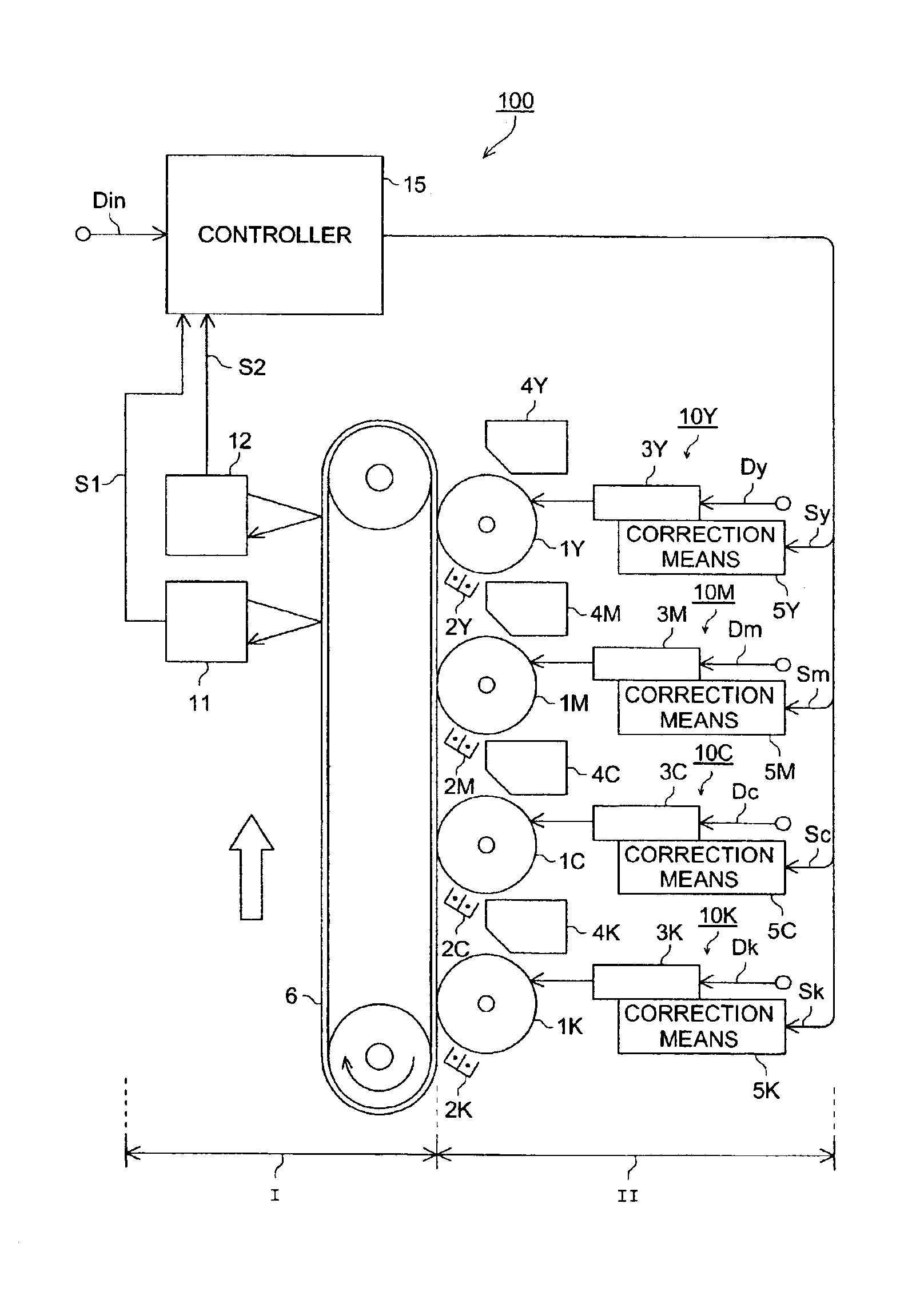
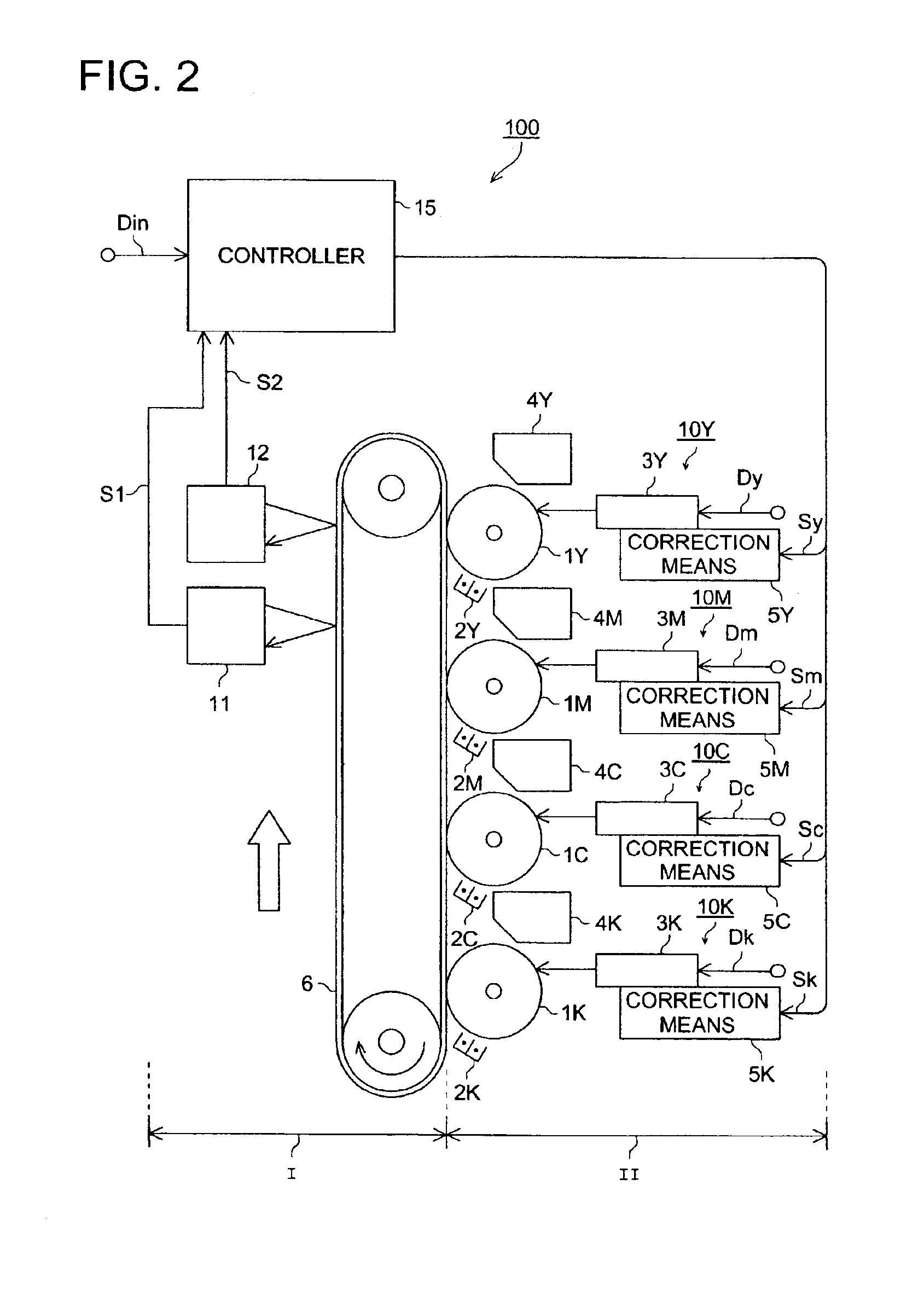
[0436]In this example, there is provided the mark detection judgement means 80 made up of the registration sensors 12, the storage device 14, and the control device 15 explained in FIG. 37; by the registration sensors 12, the surface state of the registration mark formation area of the photoreceptor belt 60 is detected, and in the control device 15, a detection unable flag FG is prepared. This detection unable flag FG is adopted as the basis of judgement concerning whether or not an erroneous detection is to be made by the registration sensors 12A etc. at the time of the detection of color registration marks.

[0437]With this taken as an operation condition, first, in order to detect the surface state of the registration mark formation area of the photoreceptor belt 60...

example 2

[0456]FIG. 43 is a flow chart showing an example of the operation of the color image forming apparatus 600 as the second example of the present invention.

[0457]In this example, a fuse F for detecting a new belt is attached to the photoreceptor belt 60, and a new belt unit detection circuit 90 (NEW detection means) for melting off said fuse F is provided in the control device 15; in the case where the photoreceptor belt 60 is newly used or in the case where said photoreceptor belt 60 has been just replaced with a new one, the fuse F is melted off. In accordance with the result of the judgement concerning whether the fuse F is melted off or not, the mark producing method is switched over, to carry out the detection of registration marks.

[0458]This is based on it that the fuse F is in the through-conduction state when the photoreceptor belt (the belt unit) 60 is new, and the belt unit can be judged as one in use when the fuse F is opened. As the result of this, image formation processi...

example 3

[0466]FIG. 44 is a flow chart showing an example of the operation of the color image forming apparatus 600 as the third example of the present invention.

[0467]This example is premised on the case where automatic or manual selection is set by the use of the operation means 18 shown in FIG. 16, and on the basis of this, either the first adjustment mode or the second adjustment mode is set.

[0468]With this taken as a condition of operation, the control is bifurcated in the control device 15 through the setting of automatic or manual selection in the step R1 of the flow chart shown in FIG. 44. Automatic or manual selection is set by the operation screen P1 for key operation. If the selection bit A of the software switch SW3 is “0”, to set automatic selection, the procedure moves to the step R2, where it is judged by the control device 15 whether the detection unable flag FG is “1” or “0”. If the detection unable flag FG=0, the procedure moves to the step R4, where the first adjustment mo...


PUM

PropertyMeasurementUnit
humidityaaaaaaaaaa
temperatureaaaaaaaaaa
thicknessaaaaaaaaaa

Abstract

In an image forming apparatus for forming a color image by superposing component color images, a control device obtains position data representing a forming position of each of plural registration mark images for the component color images with respect to a positional reference value arbitrarily determined, divides the position data into each of a unit reference range representing a range in which one mark image is formed, converts the position data divided for each unit reference range into those based on respective reference values representing the front edge of the unit reference ranges, extracts the position data representing ranges common to the mutually overlapping ranges each of which is represented by a couple of position data corresponding to the rising and falling edges of a passage timing pulse as read position data of the mark image of the component color, and calculates the amounts of positional deviations of the component color images from one another on the basis of the position data extracted.

Description

BACKGROUND OF THE INVENTION[0001]This invention relates to a color image forming apparatus such as a tandem-type color printer or copying machine and a complex machine of these having an intermediate transfer belt or a photoreceptor belt and an image forming method suitably applied thereto.[0002]In recent years, a tandem-type color printer or copying machine or a complex machine of these has been used in many cases. In these color image forming apparatus, there are provided exposure means, developing devices, and photoreceptor drums for the respective colors of yellow (Y), magenta (M), cyan (C), and black (BK), an intermediate transfer belt,. and a fixing device.[0003]For example, in the exposure means for the color Y, an electrostatic latent image is formed on the photoreceptor drum on the basis of arbitrary image information. In the developing device, a color image is formed through the deposition of toner particles of the color Y on the electrostatic latent image formed on the ph...

Claims


Application Information

Patent Timeline
Patent Type & Authority Patents(United States)
IPC IPC(8): G03G15/01B41J29/393G03F3/08G06F15/00G06K15/12H04N1/50
CPCB41J29/393G03G15/0194G06K15/129H04N1/506G03G2215/0119G03G2215/0161
Inventor NISHIKAWA, EIJIMARUYAMA, HIROYUKIARAI, HIROYUKIMOTOI, TOSHIHIROIZUMIYA, KENJIOKUTOMI, RYUJIKISHI, SHINOBUOGATA, SATOSHIOZAWA, KENICHIUEDA, TADAYUKIHIGASHI, YUMIKO
Owner KONICA CORP
Why Eureka
Try Eureka