Digital signal transmission system and method of displaying transmission condition in digital signal transmission system

a digital signal and transmission system technology, applied in the direction of transmission monitoring, receiver monitoring, instruments, etc., can solve the problem that the operator of the orientation adjustment of the antenna cannot view the transmitting sid

Inactive Publication Date: 2005-06-28
KOKUSA ELECTRIC CO LTD
View PDF9 Cites 19 Cited by
  • Summary
  • Abstract
  • Description
  • Claims
  • Application Information

AI Technical Summary

Benefits of technology

[0083]According to the invention, when at least ghost-status imaging signal or additionally the BER imaging signal and field intensity imaging signal are displayed together on a video monitor, the transmission-conditions based on those imaging signals can be comprehensively viewed in association with each other, and thus be correctly grasped. Therefore, the antenna alignment operator can work for alignment effectively by viewing these images.
[0084]Moreover, according to the invention, the information of field strength, BER, and mixed state of reflected waves (ghost-status) that indicate the conditions of the signal transmission from the mobile relaying stations is transmitted from the OFDM transmission system to a remote place, or a studio as the final receiving stage, where the transmission-conditions can be displayed, and thus the director or other persons can correctly grasp the transmission-conditions.

Problems solved by technology

However, for beyond-the-horizon transmission, the antenna orientation adjustment operator cannot view the transmitting side.
Thus, in the digital transmission system, since it is not easy to image the received signal on the receiving antenna side on which the antenna adjustment operator engages in the adjustment, the alignment is often performed by use of the aforementioned exclusive field intensity or BER level meter.

Method used


Image

  • Digital signal transmission system and method of displaying transmission condition in digital signal transmission system
  • Digital signal transmission system and method of displaying transmission condition in digital signal transmission system
  • Digital signal transmission system and method of displaying transmission condition in digital signal transmission system

Examples


Embodiment Construction

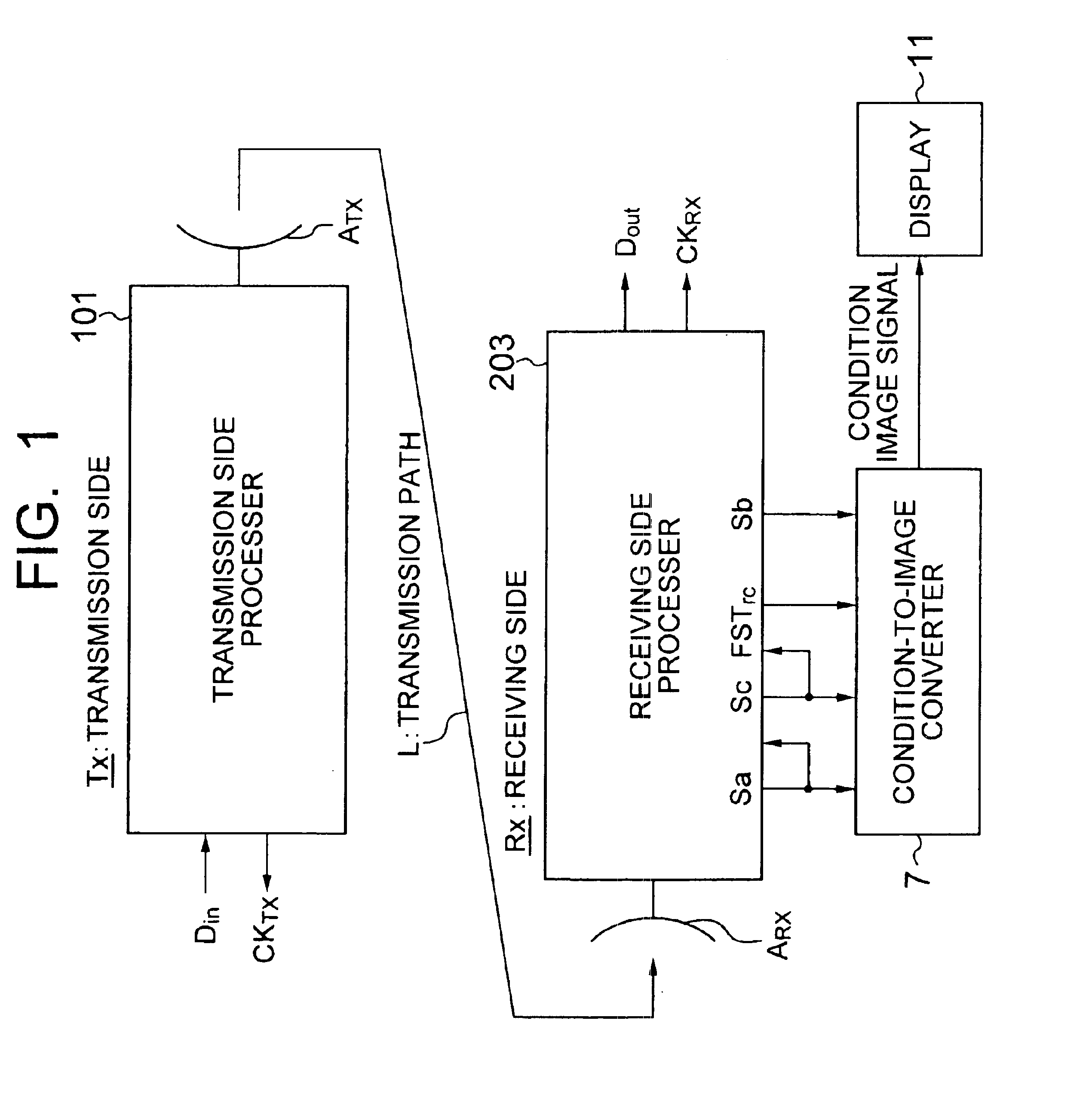
[0171]FIG. 1 shows the whole construction of an OFDM modulation type transmission system according to the invention. The construction and operation of chiefly the receiving side will be described.

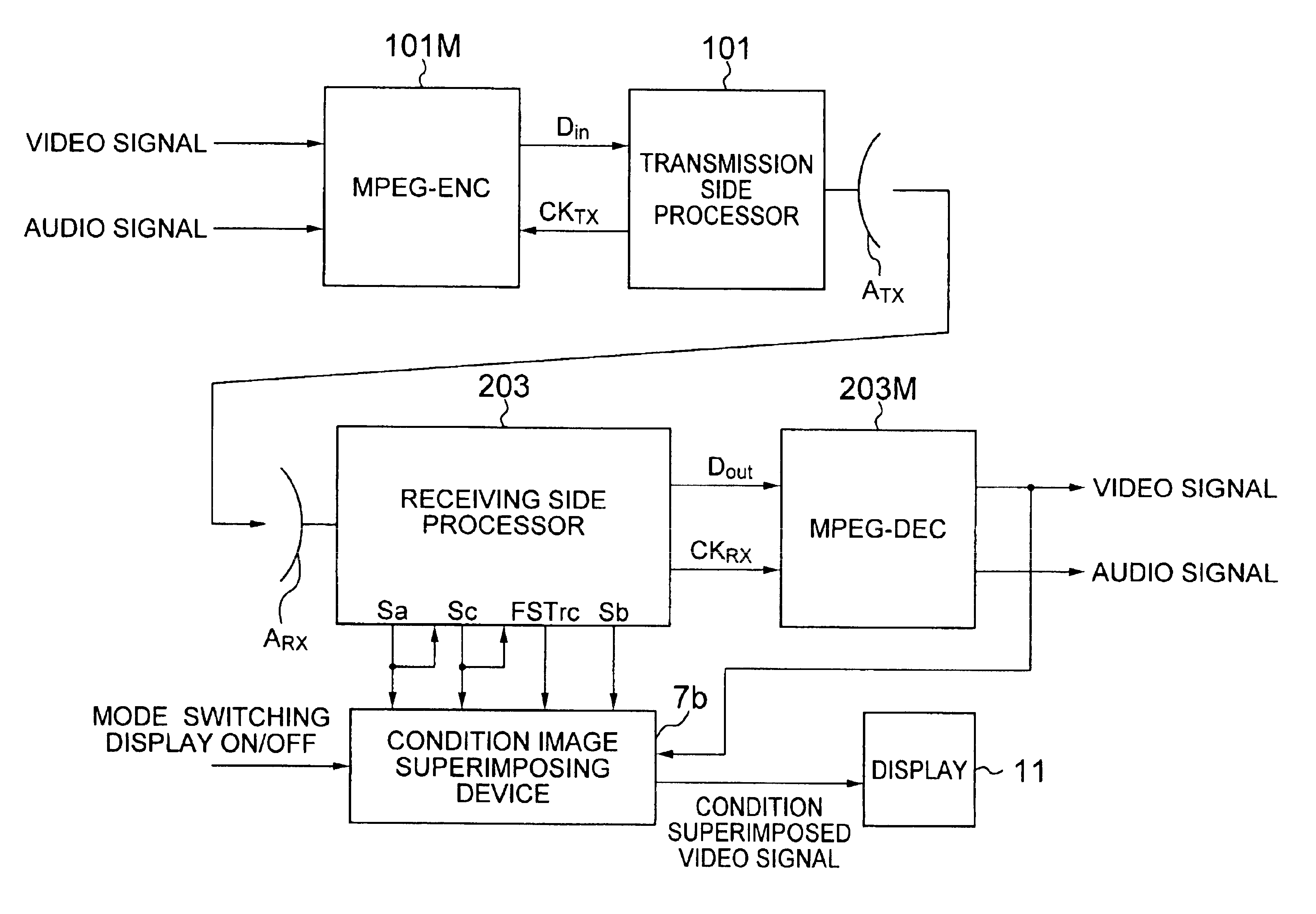
[0172]This transmission system has the transmission-side processor 101 on the transmitting side Tx as shown in detail in FIG. 17, the receiving-side processor 203 on the receiving side Rx as shown in detail in FIG. 17, a transmission-condition-to-image converter 7, and a video display 11 as shown in FIG. 1.

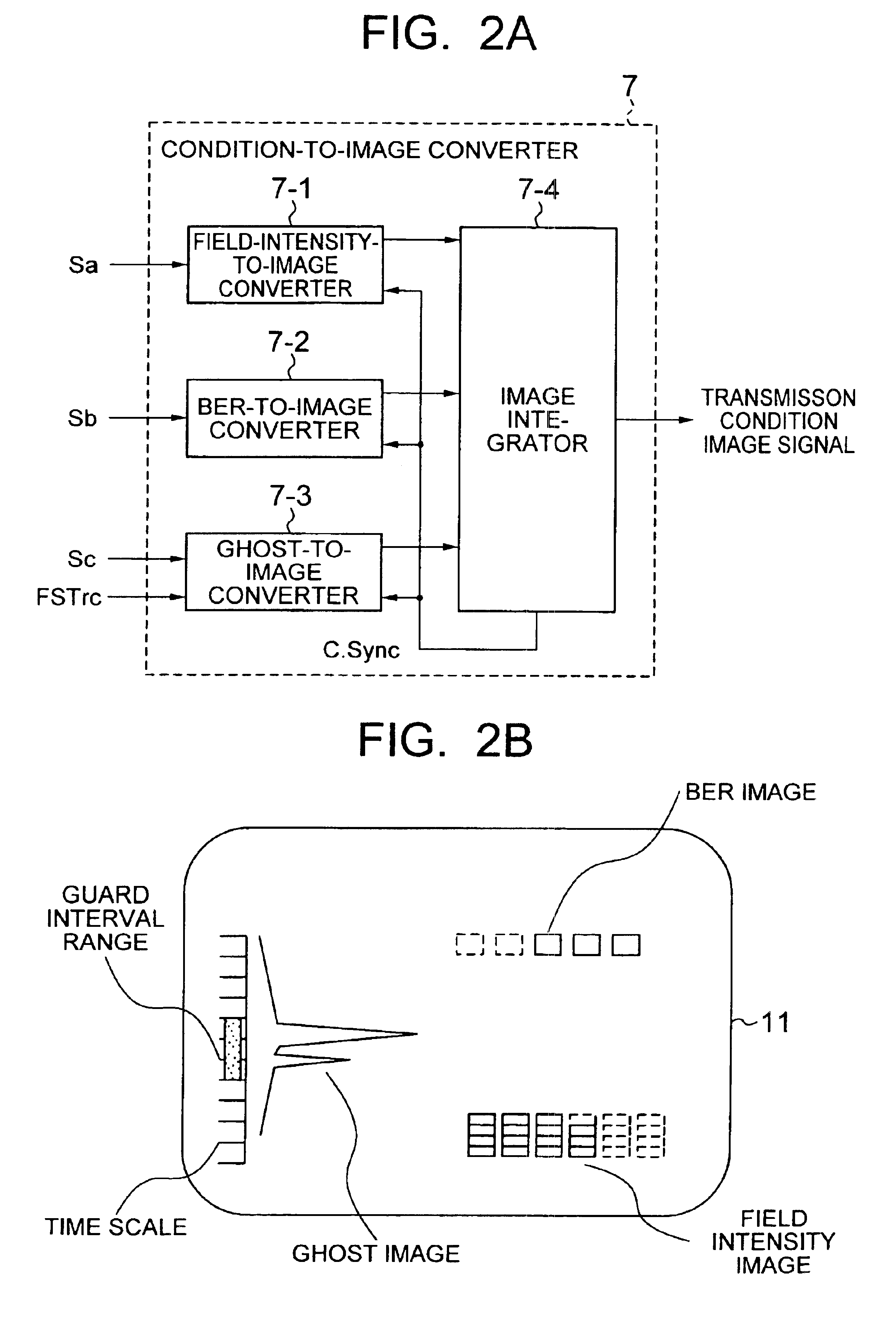
[0173]Referring to FIG. 1, on the receiving side Rx, the AGC control signal Sa indicating an electric field intensity that is produced from the receiving-side processor 203, the correlation output Sc such as a correlation value signal and the signal Sb indicating BER are supplied to the transmission-condition-to-image converter 7. Also, the pulse FSTrc as the operation timing reference from the receiving-side processor 203 is supplied to the transmission-condition-to-image converter 7. Th...


PUM


Abstract

A digital signal transmission system using a digital modulation system comprising a digital signal transmitter having a first digital signal processing unit and a digital signal receiver receiving a digital signal from the transmitter, wherein the digital signal receiver comprising a second digital signal processing unit for processing the digital signal from the transmitter and outputting a digital demodulated signal and a correlation value signal, a signal converter coupled with the second digital signal processing unit and supplied the correlation value signal therefrom for generating a waveform indicating a transmission condition including a main wave in response to the correlation value signal, and a display coupled with the signal converter for displaying the waveform indicating a transmission condition in the digital transmission system.

Description

BACKGROUND OF THE INVENTION[0001]The present invention relates to a digital signal transmission system using a digital modulation system such as orthogonal frequency division multiplex (OFDM) modulation system.[0002]In recent years, European countries, the United States of America, and Japan have already put digital broadcasting into operation or some of them are considering digital broadcasting. The OFDM modulation system is regarded as the most likely prospect for digital broadcasting.[0003]This OFDM modulation system is a kind of multi-carrier modulation system, and is the sum of a large number of digitally modulated carrier waves. In addition, each carrier is modulated by QPSK (Quadrature Phase Shift Keying), and the resultant wave of all the modulated carriers is the OFDM signal.[0004]Here, for the OFDM signal, first the QPSK signal, ak(t) of each carrier can be expressed by the following equation.ak(t)=ak(t)·cos(2πkft)+bk(t)·sin(2πkft)  (1)where k is the carrier number, and ak...

Claims


Application Information

Patent Timeline
Patent Type & Authority Patents(United States)
IPC IPC(8): H04L1/24H04B17/00
CPCH04L1/24H04B17/309H04B17/23H04B17/327
Inventor MIYASHITA, ATSUSHIWAGATSUMA, YOSHIKATSUTAKESUE, HIROYUKI
Owner KOKUSA ELECTRIC CO LTD
Why Eureka
Try Eureka