
Method of estimating location of abnormality in fluid feed pipeline network

a technology of fluid feed pipeline and abnormality, which is applied in the direction of fluid tightness measurement, instruments, machines/engines, etc., can solve the problems of affecting the accuracy of estimation, the inability to install flowmeters in existing pipeline networks, and the change in flow rate and water pressure in pipelines, so as to achieve quick estimation and increase the accuracy of estimation

Inactive Publication Date: 2005-06-28
ENEGENE
View PDF23 Cites 58 Cited by
  • Summary
  • Abstract
  • Description
  • Claims
  • Application Information

AI Technical Summary

Benefits of technology

[0009]It is an object of the present invention to provide a method of estimating the location of an abnormality in a fluid feed pipeline network that can offer a technology of quickly estimating the location of damage in a pipeline from information on water pressure. In other words, the method can provide emergency information.
[0010]Another object of the present invention is to provide a method of estimating the location of an abnormality in a fluid feed pipeline network that uses data at a point at which the amount of change at each measuring point becomes a maximum as data for forming either a fitting curve in a region where the amount of change gradually increases from the supply source of the fluid or a fitting curve in a region where the amount of change gradually decreases from the supply source of the fluid, and thus, the method uses a plurality of pairs of fitting curves so that the accuracy of estimation is increased.

Problems solved by technology

When an earthquake damages a water distribution pipeline and a water leakage occurs, the flow rate and the water pressure in the pipeline change.
However, it is practically difficult to newly install a number of flowmeters in an existing pipeline network.
When a large earthquake has caused a lot damage to a water pipeline network, recovery of the pipeline network will take one to six months.

Method used


Image

  • Method of estimating location of abnormality in fluid feed pipeline network
  • Method of estimating location of abnormality in fluid feed pipeline network
  • Method of estimating location of abnormality in fluid feed pipeline network

Examples


modified embodiment a

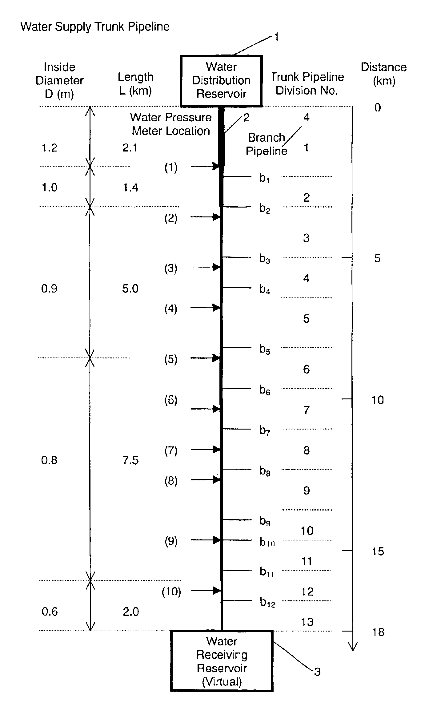
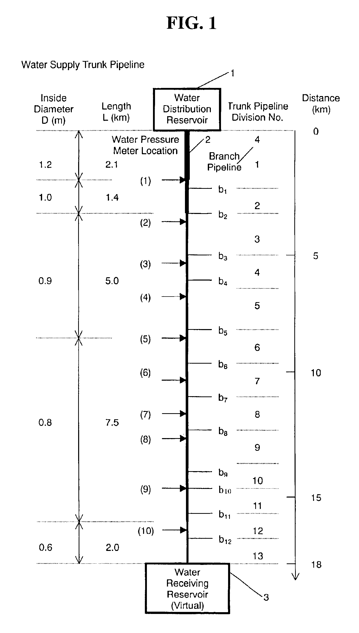
[0065]A case that the branch pipeline b6 is damaged (or the branch pipeline is opened.) will be described as Embodiment A.

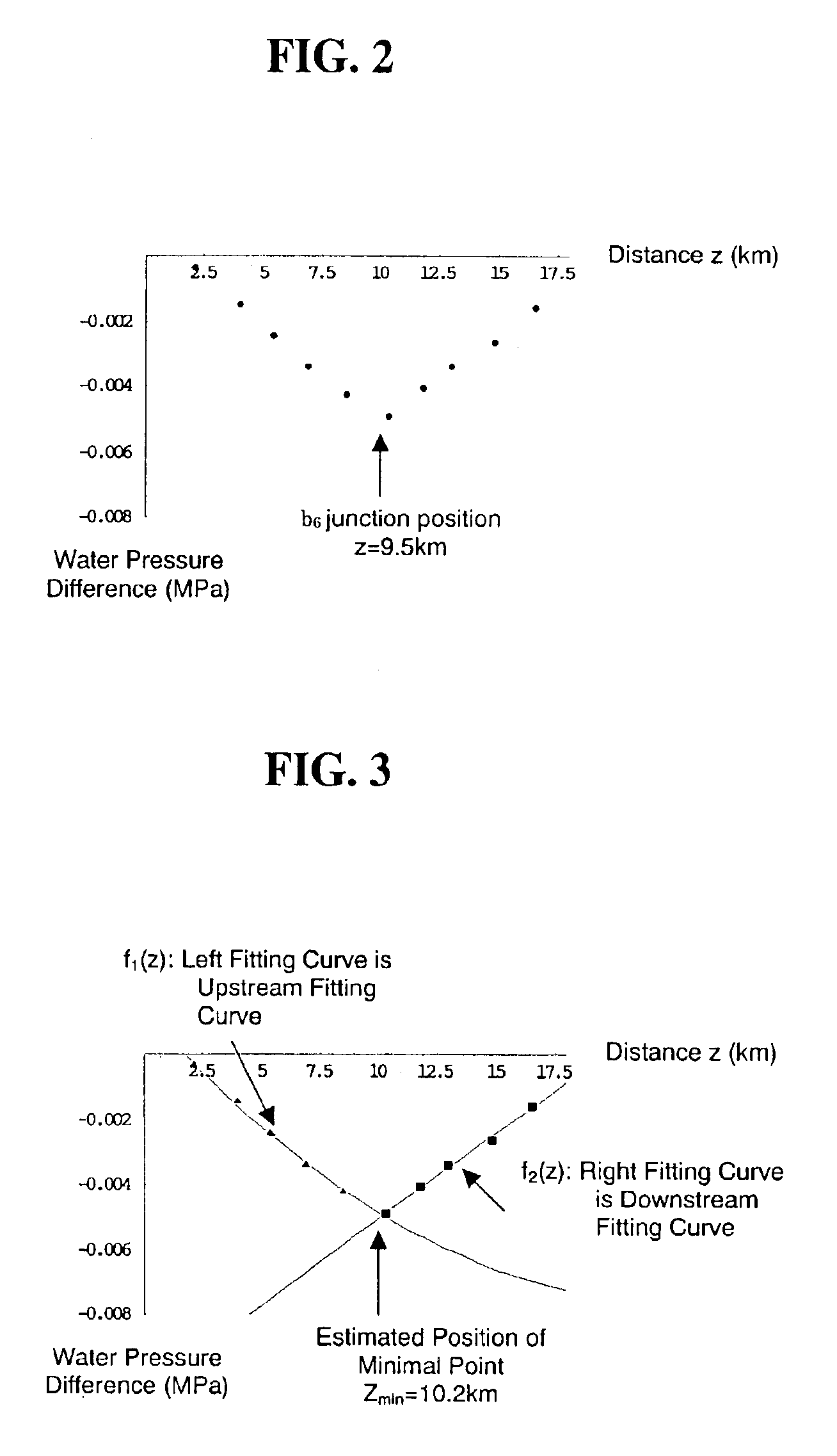
[0066]Data of the distribution of water pressure difference in the case that the branch pipeline b6 is ruptured (or the base part is opened.) is shown in FIG. 8. The minimum value of the water pressure difference of the data is −0.00488 MPa. FIG. 9 shows the case of the above (i). The left fitting curve f61,left(z) is determined with the assumption that the minimum data of water pressure difference is handled as the upstream data, and the distance z (9.7999) of the point of intersection with the right fitting curve f61,right(z) is obtained. Then, a first minimal value Pmin of water pressure difference (−0.00472185 MPa) is obtained from this distance, using Expressions 1. Associated expressions and results of the calculation are shown in Expressions 1.

Expressions 1

[0067]Left fitting curve

 f61,left(z)=0.0013204−0.000787858z+0.0000174794z2

[0068]Right fitting curve

f6...

modified embodiment b

[0085]A case that the branch pipeline b3 is damaged (or the branch pipeline is opened.) will be described as Embodiment B.

[0086]The minimum value of the water pressure difference of the data is −0.00198 MPa. FIG. 12 shows the case of the above (i). The left fitting curve f31,left(z) is determined with the assumption that the minimum data of water pressure difference is handled as upstream data, and the distance z (5.34873) of the point of intersection with the right fitting curve f31,right(z) is obtained. Then, a first minimal value Pmin of water pressure difference (−0.00196011 MPa) is obtained from this distance, using Expressions 4. Associated expressions and results of the calculation are shown in Expressions 4.

Expressions 4

[0087]Left fitting curve

f31,left(z)=0.00113813−0.000768751z+0.0000354295z2

[0088]Right fitting curve

f31,right(z)=−0.0027828+0.000157652z−7.17977×10⁻⁷z2

[0089]Minimal position of water pressure difference

f31,left(z)=f31,right(z)→Z=5.34873

[0090]Minimal value of w...

modified embodiment c

[0105]A case that the branch pipeline b9 is damaged (or the branch pipeline is opened.) will be described as Embodiment C.

[0106]The minimum value of the water pressure difference of the data is −0.00713 MPa. FIG. 15 shows the case of the above (i). The left fitting curve f91,left(z) is determined with the assumption that the minimum data of water pressure difference is handled as upstream data, and the distance z (13.96) of the point of intersection with the right fitting curve f91,right(z) is obtained. Then, a first minimal value Pmin of water pressure difference (−0.00803199 MPa) is obtained from this distance, using Expressions 7. Associated expressions and results of the calculation are shown in Expressions 7.

Expressions 7

[0107]Left fitting curve

f91,left(z)=0.000414769−0.000308758z−0.0000212333z2

[0108]Right fitting curve

f91,right(z)=−0.0297906+0.00155882z

[0109]Minimal position of water pressure difference

f91,left(z)=f91,right(z)→Z=13.9583

[0110]Minimal value of water pressure dif...


PUM


Abstract

A method of detecting the location of a failure (e.g., a sudden leak) in a fluid pipeline network, which can be suitably used for estimation of the location of a failure in a water pipeline network, includes the steps of periodically measuring a flow rate or fluid pressure with sensors arranged at a plurality of measuring points along a pipeline in a water pipeline network; comparing a latest measured amount and a previous measured amount at each measuring point to determine if an amount of change at an arbitrary point has exceeded a predetermined value; and calculating a position at which an amount of change becomes maximum, the position being calculated from the magnitudes of the amounts of changes in respective measured values at the time of the detection. The pipeline network may be a water supply and distribution pipeline network which includes a trunk pipeline and branch pipelines.

Description

BACKGROUND OF THE INVENTION[0001]1. Field of the Invention[0002]The present invention relates to a method of estimating the location of a failure or the like in a fluid feed pipeline network, and more particularly relates to a method of determining the location of a failure in a fluid feed pipeline network which can be suitably used for estimation of the location of a failure in a water pipeline network.[0003]2. Description of the Related Art[0004]There have been various proposals with respect to monitoring abnormal conditions of a lifeline such as a water pipeline network. The Japanese Patent No. 3,082,965 discloses an invention of a method of monitoring a water pipeline and an apparatus therefor using a memory card. The object of the Japanese Unexamined Patent Application Publication No. H09-43010 is to shorten a restoration time of a system by quickly detecting the specific location of a failure in a lifeline. A number of sensors dedicated to detecting failures and the like are i...

Claims


Application Information

Patent Timeline
Patent Type & Authority Patents(United States)
IPC IPC(8): G01M3/28G01D21/00G06F19/00
CPCG01M3/2807
Inventor MIZUSHINA, SHIZUOADACHI, ATSUSHIFUJIWARA, TAKAHIRO
Owner ENEGENE
Learn More