Flexible heat pipe structure and associated methods for dissipating heat in electronic apparatus

a flexible, heat pipe technology, applied in the direction of electrical apparatus casings/cabinets/drawers, semiconductor/solid-state device details, instruments, etc., can solve the problems of relatively high weight and cost, complex structure, and large assembly requirements, so as to increase the overall heat transfer contact area and increase the circularity of the inner side surface

Inactive Publication Date: 2005-07-05
HEWLETT PACKARD DEV CO LP
View PDF7 Cites 12 Cited by
  • Summary
  • Abstract
  • Description
  • Claims
  • Application Information

AI Technical Summary

Benefits of technology

[0014]Representatively, this radially outwardly deforming step includes the steps of restraining the outer side surface of the generally tubular structure against radial enlargement thereof while axially forcing a diametrically oversized cylindrical structure through the interior of the generally tubular structure,

Problems solved by technology

These previously utilized heat pipe-based heat transfer structures have typically carried with them the undesir

Method used


Image

  • Flexible heat pipe structure and associated methods for dissipating heat in electronic apparatus
  • Flexible heat pipe structure and associated methods for dissipating heat in electronic apparatus
  • Flexible heat pipe structure and associated methods for dissipating heat in electronic apparatus

Examples


Embodiment Construction

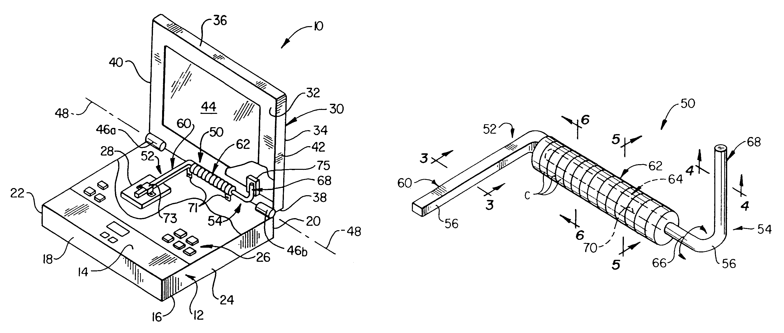
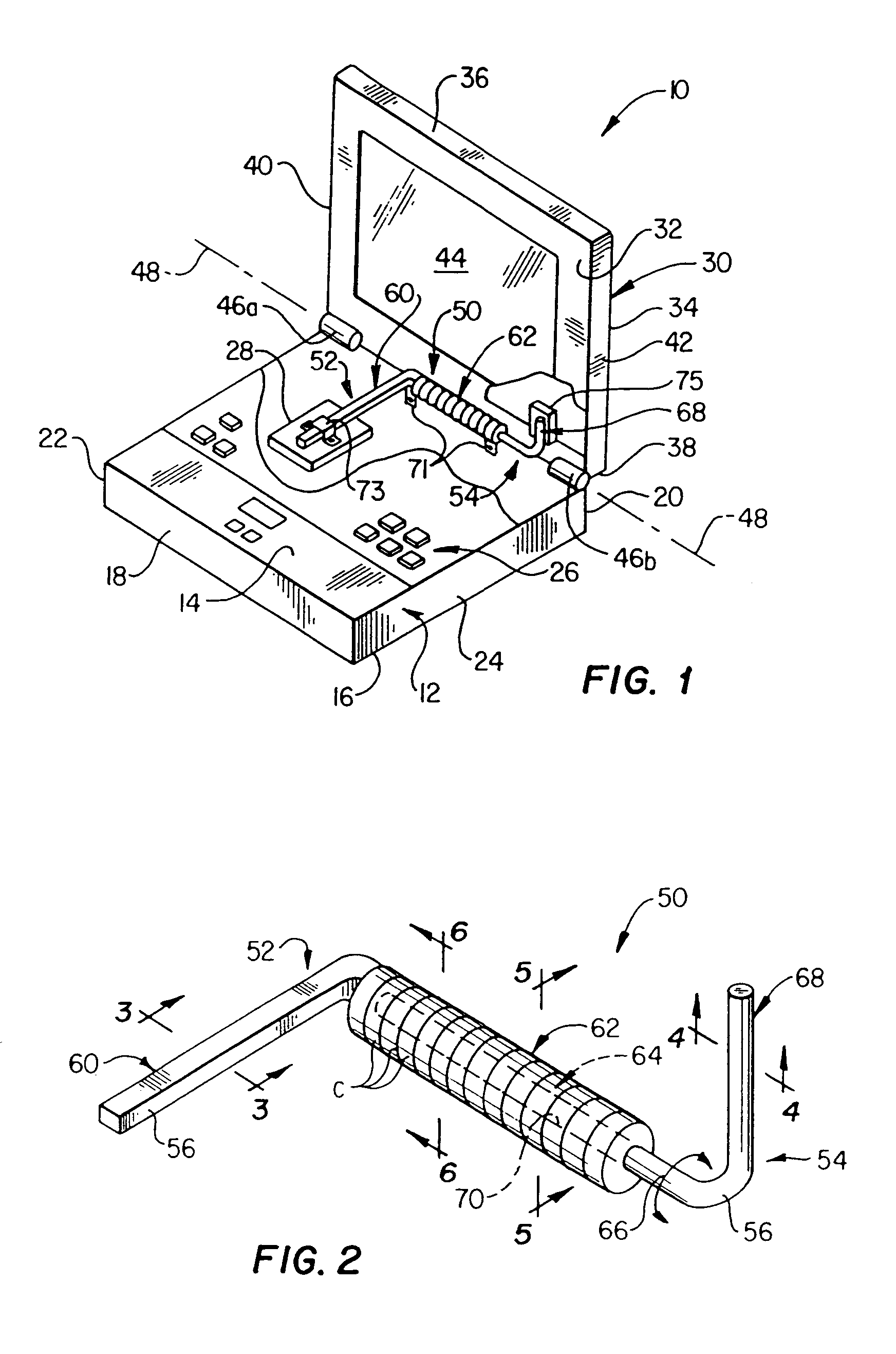
[0024]Specially designed electronic apparatus 10, which is representatively in the form of a portable notebook computer, is perspectively illustrated in simplified form in FIG. 1 and embodies principles of the present invention. Notebook computer 10 includes a rectangular base housing 12 having top and bottom side walls 14 and 16, front and rear side walls 18 and 20, and left and right end walls 22 and 24. A keyboard 26 is operatively disposed on the top side wall 14, within a suitable opening therein, and various electronic components, such as the schematically depicted microprocessor 28, are carried within the interior of the base housing 12 beneath its top side wall 14 and keyboard 26. During operation of the computer 10, the microprocessor 28 generates a considerable amount of heat which, in a manner subsequently described herein, is dissipated from the base housing 12 using principles of the present invention.

[0025]The computer 10 also includes a rectangular lid housing structu...


PUM

PropertyMeasurementUnit
Diameteraaaaaaaaaa
Circumferenceaaaaaaaaaa
Heataaaaaaaaaa

Abstract

A notebook computer has a base housing with a heat-generating microprocessor therein, and a lid housing pivotally connected to the base housing. Operating heat from the microprocessor is transferred to the lid housing, for dissipation therefrom, via a specially designed thermosyphoning heat pipe structure formed from first and second heat pipes. The first heat pipe representatively has a rectangular cross-section, an evaporating portion thermally communicated with the microprocessor, and a coiled condensing portion centered about the lid hinge line and having a circularly cross-sectioned interior side surface portion defined by flat sides of the first heat pipe. The second heat pipe has a circular cross-section, an evaporating portion pivotally received within the coiled first heat pipe portion, and a condensing portion thermally communicated with the lid housing. When the lid housing is opened and closed, the evaporating portion of the second heat pipe is rotated within the coiled first heat pipe portion and slidably engages its circularly cross-sectioned interior side portion.

Description

[0001]This application is a divisional of application Ser. No. 09 / 317,322, filed May 24, 1999 now U.S. Pat. No. 6,253,836.BACKGROUND OF THE INVENTION[0002]1. Field of the Invention[0003]The present invention generally relates to electronic apparatus and, in a preferred embodiment thereof, more particularly relates to apparatus and methods for dissipating component operating heat in electronic devices such as computers.[0004]2. Description of Related Art[0005]As the increasingly popular notebook computer continues to be provided with higher speed electronic components and correspondingly greater computing power and functionality, the need to sufficiently dissipate operating heat from high heat generating components in the computer becomes correspondingly greater.[0006]As conventionally constructed, a notebook computer has a base housing, within which the primary heat generating components (such as the computer's microprocessor) are disposed, and a substantially thinner display lid ho...

Claims


Application Information

Patent Timeline
IPC IPC(8): G06F1/20F28D15/02H01L23/427H01L23/34H05K7/20
CPCF28D15/0233F28D15/0241G06F1/203H01L23/427G06F2200/201Y10T29/49361H01L2924/0002Y10T29/49353Y10T29/49362H01L2924/00
Inventor MITCHELL, NATHAN A.
Owner HEWLETT PACKARD DEV CO LP
Why Eureka
Try Eureka