Control apparatus for internal combustion engine

a control apparatus and internal combustion engine technology, applied in electrical control, machines/engines, non-mechanical valves, etc., can solve the problems of deterioration in performance efficiency, fuel consumption, exhaust emission, etc. of the engine, and does not teach nothing about the above-described difference in operation between the variable valve control mechanism, etc., to suppress deterioration in performance efficiency, fuel consumption, exhaust emission, etc.

Inactive Publication Date: 2005-07-05
NISSAN MOTOR CO LTD
View PDF4 Cites 41 Cited by
  • Summary
  • Abstract
  • Description
  • Claims
  • Application Information

AI Technical Summary

Benefits of technology

[0006]It is accordingly an object of the present invention to provide a control apparatus for an internal combustion engine which can effectively absorb a difference or variation in intake air quantity between cylinders due to an error in installation of the variable valve control mechanisms of respective cylinder groups and can suppress deterioration in performance efficiency, fuel consumption, exhaust emission, etc. of the engine.

Problems solved by technology

Thus, there is a possibility of causing a difference in the lift, operation angle and maximum lift phase of the intake valve between the banks due to an error in installation, variations inherent in parts of the variable valve control mechanism, etc., leading to deterioration in the performance efficiency, fuel consumption, exhaust emission, etc. of the engine.
Further, although the above-described Japanese Patent Publication No. 9-203337 discloses a feedback control of the air / fuel ratio that is conducted independently of each cylinder, it does not teach nothing about how to deal with the above-described difference in operation between the variable valve control mechanisms installed on the respective banks.

Method used


Image

  • Control apparatus for internal combustion engine
  • Control apparatus for internal combustion engine
  • Control apparatus for internal combustion engine

Examples


Embodiment Construction

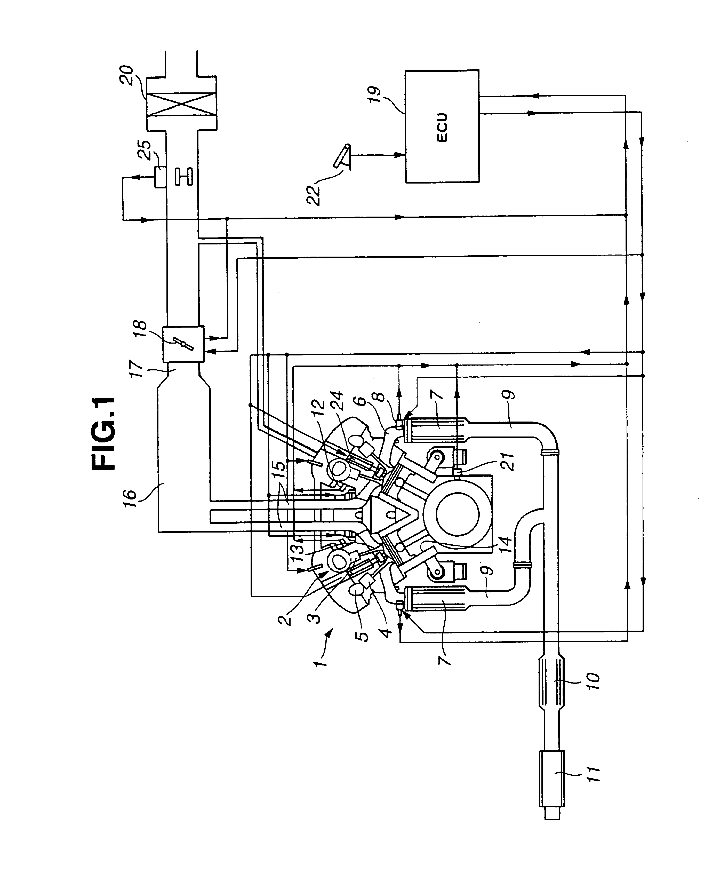
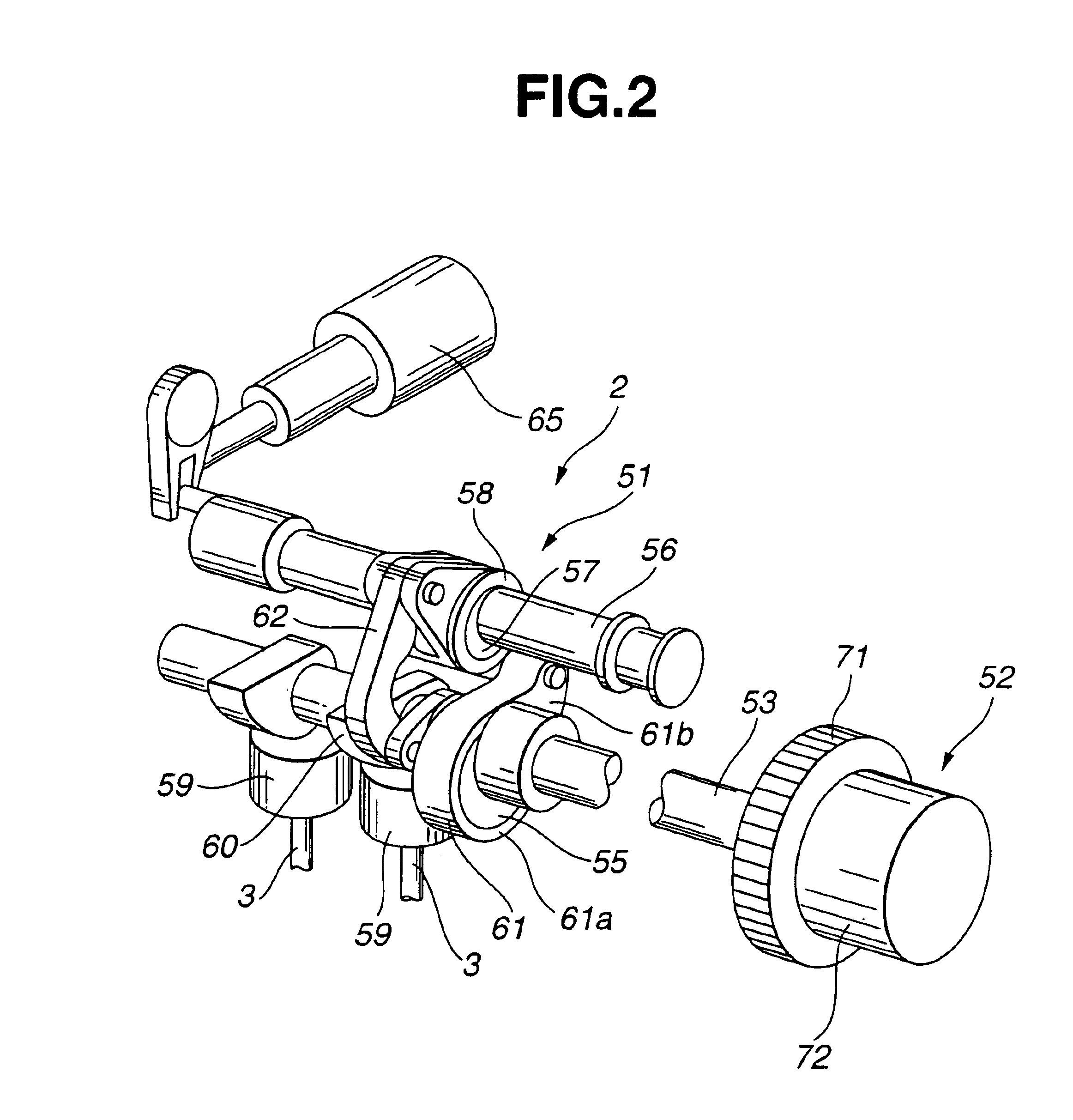
[0020]Referring first to FIG. 1, a V-type 6-cylinder gasoline engine is generally indicated by 1 and includes variable valve control mechanisms 2 disposed at respective banks (i.e., respective cylinder groups) for controlling valve timings of intake valve 3 separately at the respective banks. Engine 1 also includes valve operating mechanisms (no numeral) disposed at the respective banks for operating exhaust valves 4. The valve operating mechanisms for exhaust valves 4 are of the direct-drive type so as to drive exhaust valves 4 directly by exhaust camshafts 5 and therefore has valve lift characteristics that are always constant.

[0021]Exhaust manifolds 6 for the respective banks are connected to catalytic converters 7. Upstream of catalytic converters 7 are disposed air / fuel ratio sensors 8 for detecting the air / fuel ratio of the exhaust gas. Exhaust passages 9 for the respective banks are joined at the downstream sides of catalytic converters 7 to form a single passage that is prov...


PUM


Abstract

A control apparatus for an internal combustion engine having two cylinder groups and two variable valve control mechanisms provided to the respective cylinder groups, includes a detecting section that detects an incylinder pressure of each cylinder, a comparing section that makes a comparison between the two cylinder groups with respect to a combustion stability and a control section that varies valve lift characteristics of intake valves of one cylinder group which is larger in the average incylinder pressure than the other cylinder group in accordance with a result of comparison by the comparing section so as to make intake air quantities for the respective cylinder groups be equal to each other.

Description

BACKGROUND OF THE INVENTION[0001]The present invention relates to a control apparatus for an internal combustion engine.[0002]A variable valve control mechanism capable of varying valve lift characteristics of an intake valve continuously is disclosed in Unexamined Japanese Patent Publication No. 2002-89341 which is assigned to the same assignee of this application. The variable valve control mechanism includes in combination an operation angle varying mechanism capable of varying an operation angle of an intake valve continuously and a phase varying mechanism capable of varying a maximum lift phase of an intake valve (i.e., the phase at which the lift of the intake valve becomes maximum).[0003]Further, Unexamined Japanese Patent Publication No. 9-203337 discloses a technique for obviating a difference in air / fuel ratio between cylinders by detecting an air / fuel ratio of each cylinder through comparison between a time variation of a detection signal of an air / fuel ratio sensor and a...

Claims


Application Information

Patent Timeline
Patent Type & Authority Patents(United States)
IPC IPC(8): F02D41/00F02D13/02F01L13/00F02D41/34F02D41/14F02D35/02F02M25/07F02D41/04F02D45/00
CPCF01L13/0026F02D13/0211F02D13/0238F02D13/0261F02D41/0002F02D41/0082F02M25/0752F02M25/0753F02D35/023F01L2013/0073F01L2800/00F02D41/1443F02D41/1497F02D2041/001Y02T10/18Y02T10/42F02M26/01F02M26/45Y02T10/12Y02T10/40
Inventor MIURA, HAJIME
Owner NISSAN MOTOR CO LTD
Why Eureka
Try Eureka