Method of making an internal grooved tube

a technology of internal grooves and grooves, which is applied in the direction of manufacturing tools, drawing dies, lighting and heating apparatus, etc., can solve the problems of increasing the weight of the tube, increasing the roll diameter, and increasing the difficulty of forming grooves of a great height, so as to achieve greater fin height and high performance.

Inactive Publication Date: 2005-07-05
FURUKAWA ELECTRIC CO LTD
View PDF13 Cites 14 Cited by
  • Summary
  • Abstract
  • Description
  • Claims
  • Application Information

AI Technical Summary

Benefits of technology

[0012]After having made various trials and errors, the present inventors found out the fact that the heat transfer performance of an internal grooved tube is at its highest when a width of each internal groove in the tube axial direction (the longitudinal direction) in the heat exchanger tube has a fixed relation to a groove height, resulting in the proposal of the present invention. It is an object of the present invention to provide an internal grooved tube, which permits the realization of higher performance, lightweight and miniaturization, without the need for greater internal groove height (greater fin height).
[0013]Another object of the present invention is to provide an internal grooved tube manufacturing method, which makes it possible to machine a heat exchanger tube satisfying the above object smoothly at high speed without causing breakage.

Problems solved by technology

However, with greater groove height (fin height), it is necessary to increase a thickness of a tube in proportion to the groove height, resulting in an increase in tube weight.
Besides, large crushes of fins formed in the tube occur in tube expansion (by press-fitting a rod provided with a net ball at the tip for tube expansion to fix the tube to aluminum fins) for incorporating the tube into the heat exchanger, and as a result, the grooves formed to be of a great height could not often take satisfactory effect.
Among the internal grooved tube manufacturing methods, the method of permitting the planetary revolution of a plurality of rolls having axes held by the holder around the circumference of the blank tube in a location of the grooved plug inserted as disclosed in Japanese Patent Laid-open No. 54-37059 described the above requires a lubricating mechanism between the roll and the roll axis, in addition to the holder, for revolution of the rolls at high speed to increase a machining speed, resulting in an increase in roll diameter and also a complication of structure.
For that reasons, an increase in number of revolutions of the rolls hinders the stability of the revolution of the roll and its rotation axis, and therefore, it is not possible to hold a stable orbit of revolution, resulting in a difficulty in increasing a grooving (rolling) speed.
However, when the grooves of the grooved plug have a large lead angle to the axis, breakage (tear-off) of the blank tube occurs in process of machining to hinder higher-speed machining in spite of adding more balls.
Thus, there has been a limit to manufacture of a high-performance heat exchanger tube having a large lead angle to the tube axis.

Method used


Image

  • Method of making an internal grooved tube
  • Method of making an internal grooved tube
  • Method of making an internal grooved tube

Examples


example 1

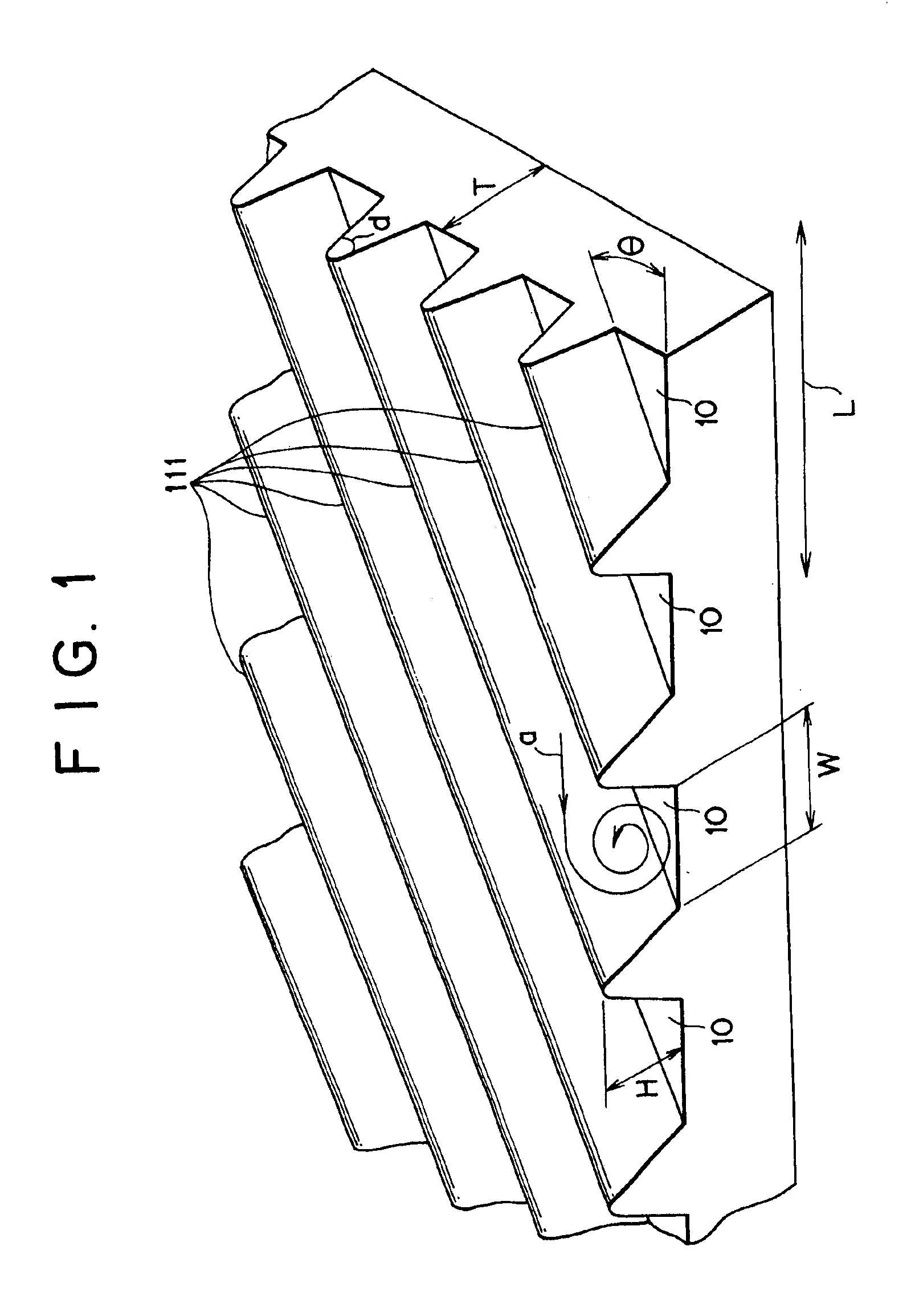
[0045]As shown in Table 1, with variations in a lead angle θ of the grooves 10 in the tube to the tube axis, heat exchanger tubes of sample Nos. 1 to 7 as the examples, in which the ratio of the groove width W in the tube axial direction L to the groove height H is in the range of 1 to 2, were manufactured, together with heat exchanger tubes of sample Nos. 8 to 19 as comparative examples, in which the ratio of the groove width W to the groove height H is in the range of less than 1 to more than 2. Then, the condensation performance of the above heat exchanger tubes was measured.

[0046]Table 1 shows the condensation performance rate when the condensation performance (reference) of the heat exchanger tube of sample No. 8 as the comparative example is assumed to be 1. In each heat exchanger tube other than those of sample Nos. 17 and 18, a copper tube having an outer diameter of 12 mm was used as a blank tube, which was then subjected to finishing into a tube having an outer diameter of...

example 2

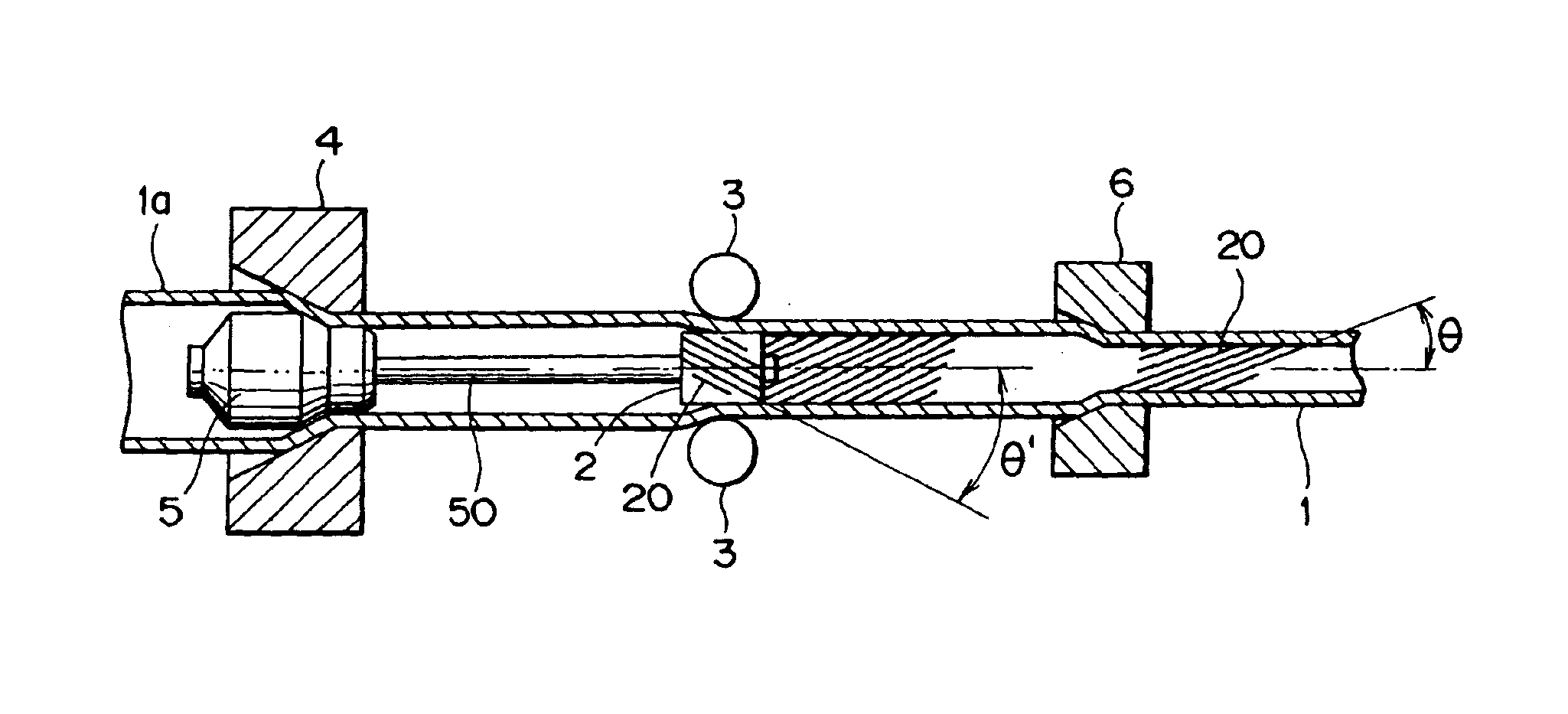
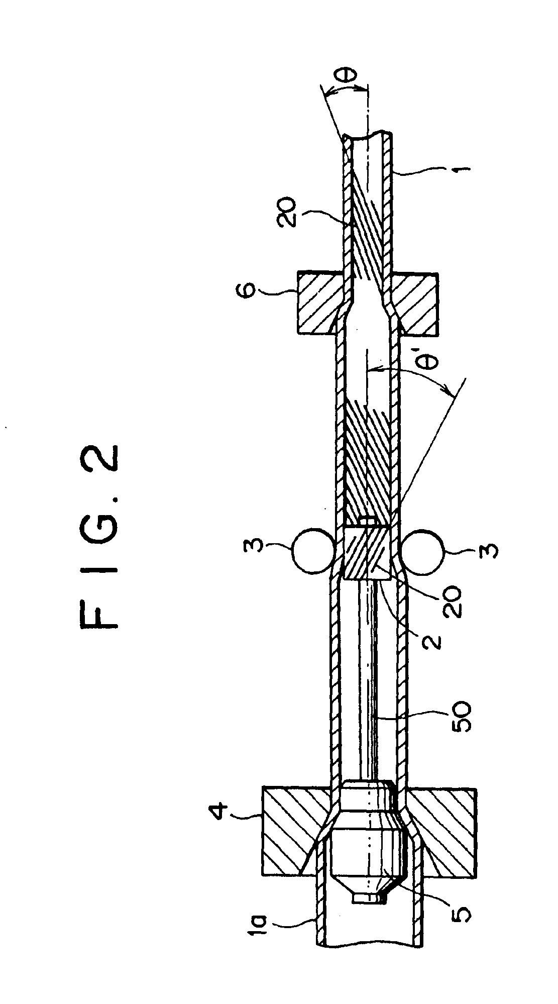
[0050]A blank tube consisting of a copper tube having an outer diameter of 12 mm was used to manufacture two kinds of heat exchanger tubes, which are 0.23 mm in groove height H, 0.46 mm in groove width W in the tube axial direction and respectively 20 and 31 degrees in lead angle θ of the grooves to the tube axis, according to the same conditions except that the number of machining balls varies from 2 to 6 without the need for a finishing die. Then, a change of drawing force was measured as to both the above heat exchanger tubes.

[0051]The results are shown in FIG. 5, in which the horizontal line is denoted as the number of balls and the vertical line as a drawing force rate. As shown in FIG. 5, in case of the heat exchanger tube having a relatively small lead angle θ (20 degrees) of the internal grooves, the drawing force increased at a substantially fixed rate with an increase in number of balls. On the other hand, in case of the heat exchanger tube having a large lead angle θ (31 ...

example 3

[0052]A blank tube consisting of a copper tube having an outer diameter of 12 mm was used to manufacture a heat exchanger tube of sample No. 7 (a lead angle θ of the grooves before finish drawing is 36 degrees, while a lead angle θ of the grooves after finish drawing is 31 degrees) as the example, together with a heat exchanger tube of sample No. 16 (a lead angle θ of the grooves before finish drawing is 20 degrees, while a lead angle θ of the grooves after finish drawing is 15 degrees) as the comparative example according to the same conditions except that the number of machining balls varies from 2 to 6. Then, a critical (maximum) grooving speed (drawing speed) was measured as to both the heat exchanger tubes.

[0053]Incidentally, the heat exchanger tube of sample No. 7 as the example was manufactured on condition that the direction of revolution of the balls and the direction of rotation of the grooved plug are matched and also on condition that both the directions are reversed. On...


PUM

PropertyMeasurementUnit
lead angleaaaaaaaaaa
angleaaaaaaaaaa

Abstract

A method of manufacturing an internal grooved tube according to the present invention includes the steps of inserting a grooved plug into a blank tube rotatably, and then pressing the blank tube against the outside surface of the grooved tube with several balls revolving both around the circumference of the blank tube and on its axis in location of the grooved plug inserted, while drawing out the blank tube longitudinally in one direction, wherein the number of balls is limited to 2 to 3. A lead angle θ of the grooves to the tube axis is preferably limited to 26 to 45 degrees.

Description

RELATED APPLICATIONS[0001]This application is a divisional of application Ser. No. 09 / 792,902, filed Feb. 26, 2001 now abandoned, the disclosure of which is incorporated in its entirety herein by reference.BACKGROUND OF THE INVENTION[0002]1. Field of the Invention[0003]This invention relates to an internal grooved tube used as a heat exchanger tube for a heat exchanger of a refrigerator and an air conditioner or the like and a method of manufacturing such an internal grooved tube, and more specifically, to an internal grooved tube having a large number of fine spiral grooves (or fins) formed on the inside surface in parallel arrangement at a certain pitch and a method of manufacturing such an internal grooved tube.[0004]2. Description of the Related Art[0005]The promotion of miniaturization, higher performance and energy conservation has been made as to a heat exchanger. In this connection, as an internal grooved tube to meet such demands, in Japanese Patent Laid-open No. 8-21696, f...

Claims


Application Information

Patent Timeline
Patent Type & Authority Patents(United States)
IPC IPC(8): B21C37/20B21C37/15F28F1/40F28F1/10B21C1/22B21C3/08B21C3/16
CPCB21C37/207F28F1/40Y10T29/49373Y10T29/49384Y10T29/49382
Inventor YAMAMOTO, KOJISUMITOMO, TETSUYAMORI, YASUTOSHIHASHIZUME, TOSHIAKI
Owner FURUKAWA ELECTRIC CO LTD
Why Eureka
Try Eureka