Polishing machine for polishing periphery of sheet

a technology for periphery and polishing machine, which is applied in the direction of grinding machine components, grinding drive, manufacturing tools, etc., can solve the problems of inability to provide a polished face, and insufficient surface roughness accuracy of the polished face of the periphery. achieve the effect of accurate polishing

Inactive Publication Date: 2005-07-05
TOKYO SEIMITSU
View PDF14 Cites 5 Cited by
  • Summary
  • Abstract
  • Description
  • Claims
  • Application Information

AI Technical Summary

Benefits of technology

[0009]In view of the above problems, it is an object of the present invention to provide a polishing machine for polishing a periphery of a sheet capable of accurately polishing the peripheral edge of the sheet including a recess portion and protrusion portion even when polishing is conducted on a sheet such as a semiconductor wafer, the peripheral edge of which has a recess portion or protrusion portion such as a notch portion or orientation-flat marking portion.
[0010]An embodiment of the polishing machine for polishing a periphery of a sheet of the present invention comprises a grinding stone shaft tilting mechanism, the tilting angle of the rotary shaft of the grinding stone of which can be changed in the tangential direction of the peripheral edge of the sheet, and the direction of tilting of which can be also changed. By the above grinding stone shaft tilting mechanism, the recess portion and the protrusion portion of the peripheral edge of the sheet can be polished with high accuracy.
[0011]According to another embodiment of the polishing machine for polishing a periphery of a sheet of the present invention, when the tilting angle of the grinding stone is adjusted according to a chamfering angle of the sheet, the peripheral edge of the sheet can be effectively and accurately polished.
[0012]According to still another embodiment of the polishing machine for polishing a periphery of a sheet of the present invention, when the recess portion or the protrusion portion of the peripheral edge of the sheet is polished, it is prescribed that a tilting direction of the rotary shaft of the grinding stone is adjusted according to the rotary angle of the sheet. Therefore, it is possible to polish the periphery in the recess portion and the protrusion portion with high accuracy.
[0014]According to still another embodiment of the polishing machine for polishing a periphery of a sheet of the present invention, it is prescribed that a polishing face of the grinding stone is formed into a face, the angle of which is the same as that of an oblique face angle of grinding stone grooves which are self-formed according to the tilting angle of the grinding stone having grooves. Since the face, the angle of which is the same as that of the oblique face of the grinding stone grooves is self-formed according to the tilting angle of the grinding stone, the number of the acting abrasive grains is increased, and the abrasive grains act uniformly. Therefore, the surface accuracy of the polished face can be enhanced.
[0015]According to still another embodiment of the polishing machine for polishing a periphery of a sheet of the present invention, a grinding stone, the degree of bonding of which is lower than that of the metal bond, is used. Therefore, the abrasive grains easily come off when an over-load is given to them, and the polished face can be prevented from being damaged.

Problems solved by technology

However, in the above conventional method of polishing the periphery of the semiconductor wafer, as the abrasive grains move only in the circumferential direction of the semiconductor wafer, stripes are formed on the polished face in the periphery of the semiconductor wafer by partial blades of the grinding stone, that is, it is impossible to provide a polished face, the surface roughness accuracy of which is sufficiently high.
When the surface roughness accuracy of the polished face of the periphery is insufficient as described above, the following problems may be encountered.
Further, fine powder gets into the cracks, which could be a cause of generating dust.
Furthermore, cleaning water staying in the cracks is vaporized in a later process, which has a bad effect on the after-process of manufacturing the wafer.
However, the effects provided by the above countermeasures are limited.
Further, when the above countermeasures are adopted, the grinding efficiency is deteriorated.
However, the above polishing method is disadvantageous as follows.
Therefore, when the semiconductor has a notch portion or orientation-flat marking portion, it is impossible to successfully polish the peripheral edge of the notch portion or orientation-flat marking portion.

Method used


Image

  • Polishing machine for polishing periphery of sheet
  • Polishing machine for polishing periphery of sheet
  • Polishing machine for polishing periphery of sheet

Examples


Embodiment Construction

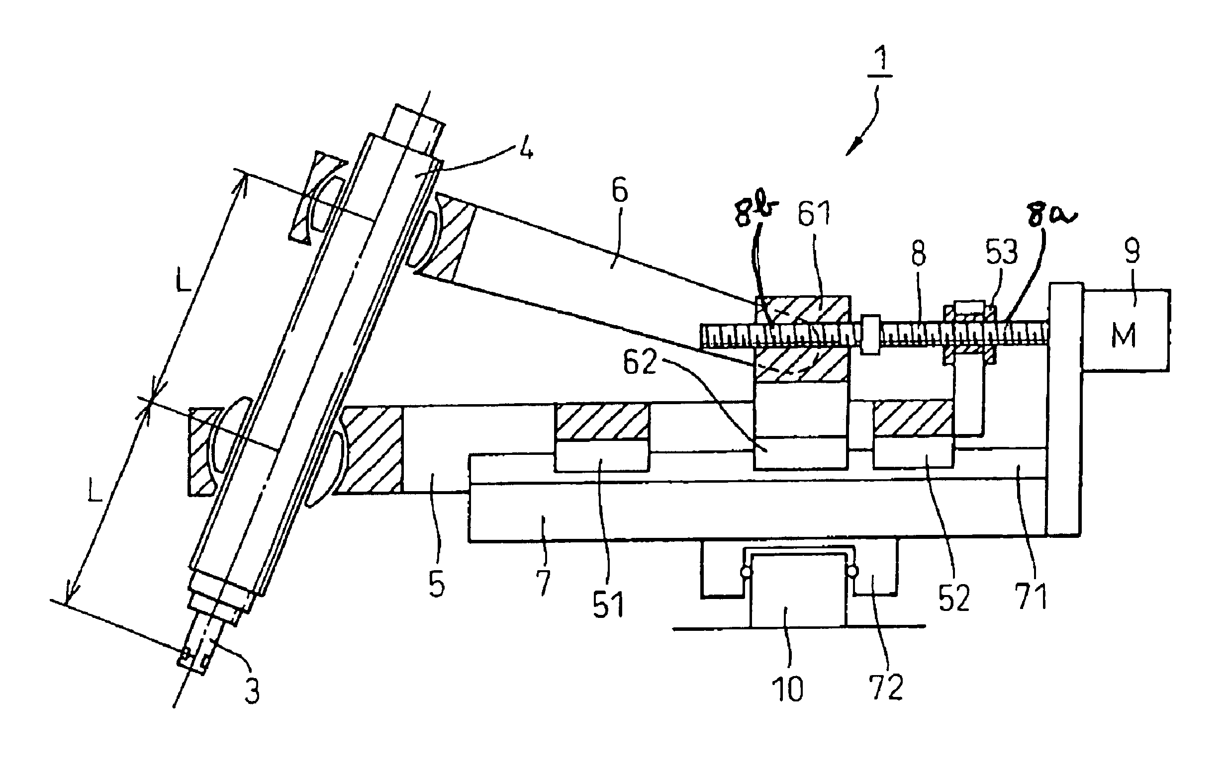
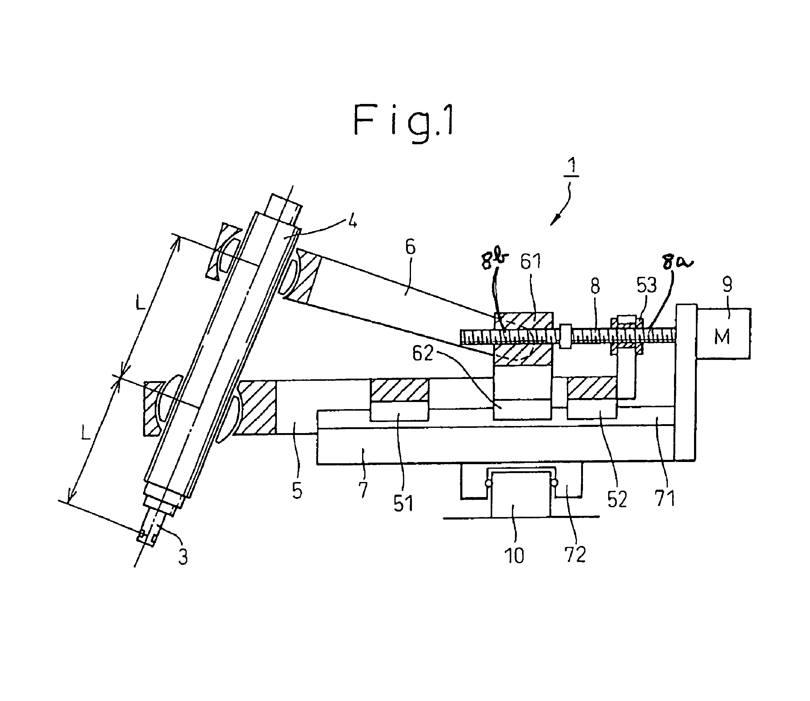
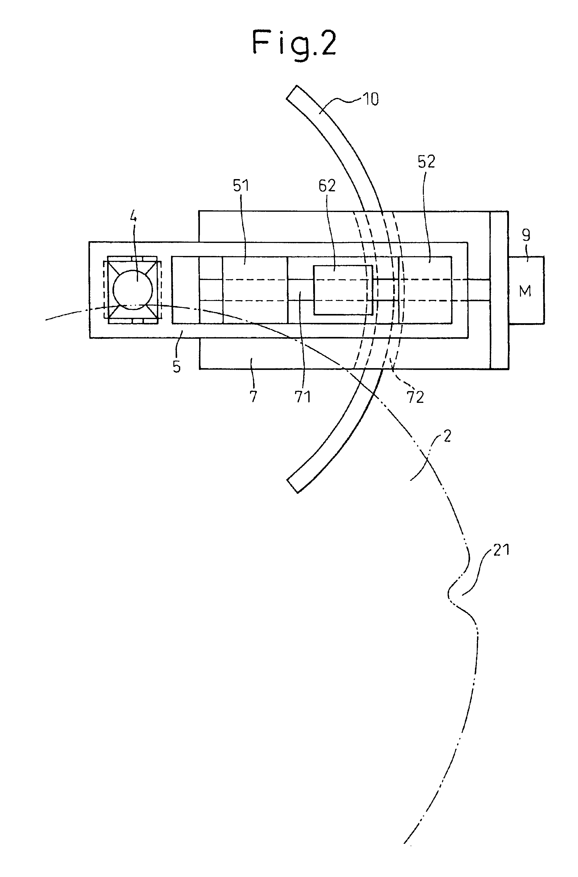
[0023]Referring to the accompanying drawings, an embodiment of the polishing machine for polishing a periphery of a sheet of the present invention will be explained as follows. FIG. 1 is a side view of the grinding stone tilting mechanism 1 of the polishing machine for polishing a periphery of a sheet of the present invention, and FIG. 2 is a plan view. The grinding section 3 for polishing the semiconductor wafer 2, which is a sheet, is fixed to the spindle 4 by a male screw portion provided on grinding section 3 which is screwed and fixed into a female screw portion provided on spindle 4. The spindle 4 is rotated by a rotation drive mechanism not shown. The spindle 4 is pivotally supported by the slider 5 at a position distant from the grinding section 3 by, for example, distance L. Further, the spindle 4 is pivotally supported by the arm 6 at a position distant from the grinding section 3 by, for example, distance 2L.

[0024]In the slider 5, the first linear bearings 51, 52, the num...


PUM

PropertyMeasurementUnit
tilting angleaaaaaaaaaa
chamfering angleaaaaaaaaaa

Abstract

A polishing machine for polishing a periphery of a sheet of the present invention comprises a grinding shaft tilting mechanism (1) capable of changing a tilting angle of a rotary shaft of a grinding stone (3) with respect to a rotary shaft of the sheet (2) and also capable of changing its tilting direction. Accordingly, in a recess portion or a protrusion portion in the periphery, when the tilting direction is changed while the tilting angle is being maintained, chamfering (polishing) can be executed with high accuracy in the same manner as that of the outer circumferential portion of the sheet.

Description

CROSS REFERENCE TO RELATED APPLICATION[0001]This application claims priority of International Patent Application No. PCT / JP01 / 07100, filed Aug. 17, 2001, which in turn claims priority of Japanese Patent Application No. 2000-248818, filed on Aug. 18, 2000.BACKGROUND OF THE INVENTION[0002]1. Technical Field of the Invention[0003]The present invention relates to a polishing machine for polishing a periphery of a sheet when a rotating grinding stone is made to come into contact with a periphery of a rotating sheet. More particularly, the present invention relates to a polishing machine for polishing a periphery of a sheet suitably used for polishing a periphery of a sheet such as a semiconductor wafer, in the periphery of which a notch or orientation-flat marking is formed.[0004]2. Background Art[0005]A surface of a semiconductor wafer, which has been cut off by means of slicing, is polished, and a periphery of the semiconductor wafer is also polished in order to prevent the occurrence ...

Claims


Application Information

Patent Timeline
Patent Type & Authority Patents(United States)
IPC IPC(8): B24B47/00B24B41/00B24B47/12B24B41/04B24B9/06
CPCB24B9/065B24B41/04B24B47/12
Inventor HONDA, KATSUO
Owner TOKYO SEIMITSU
Why Eureka
Try Eureka