Flexible implant using partially demineralized bone

Inactive Publication Date: 2005-07-05
SDGI HLDG
View PDF38 Cites 45 Cited by
  • Summary
  • Abstract
  • Description
  • Claims
  • Application Information

AI Technical Summary

Benefits of technology

[0007]In one aspect, the present invention provides a flexible bone implant. The bone implant of the present invention comprises a first bone portion, a second bone portion, and a flexible bone portion joining the first and second bone portions. The intermediate flexible bone portion permits movement of the first bone portion in relation to the second bone portion. In a preferred embodiment, the movem

Problems solved by technology

One limitation on the size of a device inserted into the disc space is the size of the opening through surrounding tissue that is available to gain access to the disc space.
Such mobilization is often limited by the anatomical structures, thus resulting in a relatively small access site in comparison to the size of the disc space.
Removal of additional ligaments and bone to enlarge an entrance to the disc space may de-stabilize and weaken the joint between two adjacent vertebra.
Moreover, excessive retraction of vessels and neural structures to create a large access opening may result in damage to these tissues.
Thus, prior procedures have been limited to placing a first device passable through the avail

Method used


Image

  • Flexible implant using partially demineralized bone
  • Flexible implant using partially demineralized bone
  • Flexible implant using partially demineralized bone

Examples


Embodiment Construction

[0023]For the purposes of promoting an understanding of the principles of the invention, reference will now be made to the embodiments illustrated in the drawings and specific language will be used to describe the same. It will nevertheless be understood that no limitation of the scope of the invention is thereby intended, such alterations and further modifications in the illustrated devices, and such further applications of the principles of the invention as illustrated therein being contemplated as would normally occur to one skilled in the art to which the invention relates.

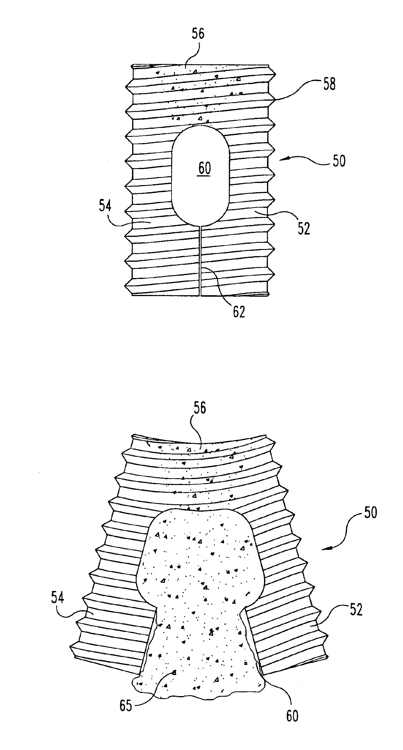
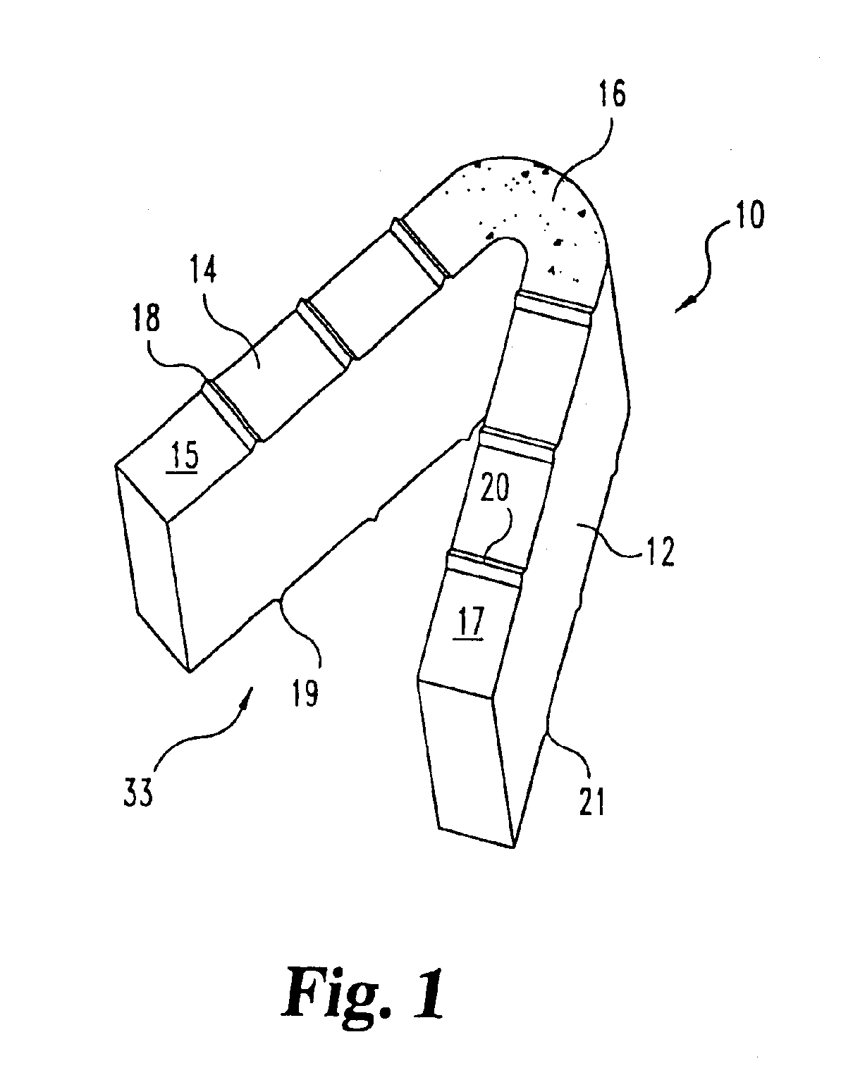
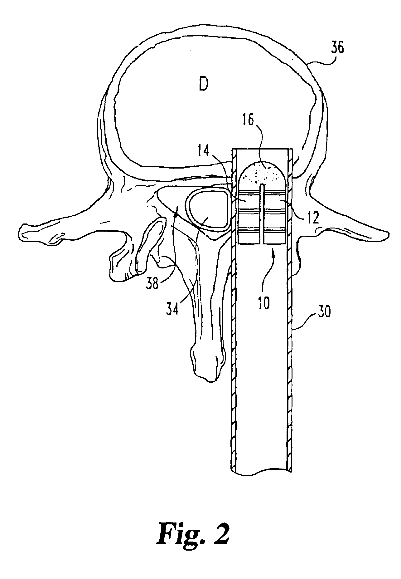
[0024]Referring now to FIG. 1, there is shown an implant according to a preferred embodiment of the present invention. Although implants according to the present invention may have many uses, the embodiment shown in FIG. 1 is particularly adapted for promoting interbody fusion in the spine. Specifically, FIG. 1 illustrates a bone implant 10 having a first substantially rigid portion 12 and a second substantial...


PUM


Abstract

Implantable devices useful for creating bony fusion particularly in intervertebral spinal fusion. The device is formed of bone and has an at least partially demineralized portion between two rigid bone portions creating an area of flexibility. In one application, the area of flexibility may be used to move the device between a reduced size insertion configuration and an expanded implanted configuration. In another use, the area of flexibility may be useful to dampen shock applied to the implant. A method is also disclosed for making the implants and inserting the implants into an intervertebral disc space to promote interbody fusion.

Description

REFERENCE TO RELATED APPLICATIONS[0001]The present application is a divisional of U.S. patent application Ser. No. 09 / 776,590 filed Feb. 2, 2001, now abandoned, which is a divisional of U.S. patent application Ser. No. 09 / 227,976 filed Jan. 8, 1999, now U.S. Pat. No. 6,206,923, which are hereby incorporated by reference in their entirety.BACKGROUND OF THE INVENTION[0002]The present invention relates to implantable fusion devices and methods for their use. More particularly, the present invention relates to interbody fusion devices formed of bone that may be utilized in spinal fusions.[0003]A variety of interbody fusion implants are available for spinal fusion procedures. These implants have been manufactured of various materials including steel, titanium, composites, allograft, xenograft or other biocompatible materials. These implants may be inserted using fixed protective tubes to protect surrounding neurological and vascular structures or through an unprotected open procedure. On...

Claims


Application Information

Patent Timeline
IPC IPC(8): A61F2/44A61F2/46A61L27/00A61L27/36A61B17/88A61F2/00A61F2/30A61F2/28
CPCA61F2/4455A61F2/447A61F2/4611A61L27/3608A61L27/365A61L27/3658A61L27/3683A61L27/3687A61F2/28A61F2/30724A61F2/3094A61F2/442A61F2002/2835A61F2002/2839A61F2002/30018A61F2002/30059A61F2002/30131A61F2002/30153A61F2002/30154A61F2002/30176A61F2002/302A61F2002/30224A61F2002/30563A61F2002/30565A61F2002/30579A61F2002/30596A61F2002/30777A61F2002/30795A61F2002/30848A61F2002/3085A61F2002/30879A61F2002/30892A61F2002/30894A61F2002/4475A61F2230/0013A61F2230/0019A61F2230/0021A61F2230/0054A61F2230/0065A61F2230/0069A61F2250/0029A61L2430/38Y10S623/919A61F2310/00359A61F2002/30014A61F2002/30594A61F2002/30845A61F2002/30593
Inventor BOYD, LAWRENCE M.PAFFORD, JOHN A.
Owner SDGI HLDG
Why Eureka
Try Eureka