Unlock instant, AI-driven research and patent intelligence for your innovation.

Capacitive test point voltage and phasing detector

a capacitive test point and detector technology, applied in the direction of noise figure or signal-to-noise ratio measurement, frequency to phase shift conversion, instruments, etc., can solve the problem of giving inaccurate voltage readings at capacitive test points, and achieve accurate detection of presence, low input impedance, and low input impedance

Inactive Publication Date: 2005-07-05
THOMAS & BETTS INT INC
View PDF7 Cites 0 Cited by
  • Summary
  • Abstract
  • Description
  • Claims
  • Application Information

AI Technical Summary

Benefits of technology

[0007]It is a further object of the present invention to provide an apparatus and method of ensuring that both the capacitive test points are energized indicating that the voltage is present at both the capacitive test points. This protects the possibility of errors occurring if both the points are not energized. In other words, the present invention provides a capacitive test point voltage and phasing detector which determines the presence of voltage at both the capacitive test points, which prevents it from providing an indication that the voltages are in or out of phase unless both the capacitive points are energized. This further eliminates any possibility of errors that might occur in determining the phase angle relationship between the two capacitive test points.
[0008]It is another object of the present invention to provide a capacitive test point voltage and phasing detector which has a very low input impedance minimizing the effects of contamination on the capacitive test point insulation surface. Thus, giving an even more reliable reading of the phase angle relationship between the two capacitive test points.
[0009]It is still a further object of the present invention to provide a capacitive test point voltage and phasing detector which is capable of accurately detecting the presence of voltage in the capacitive test points independent of the voltage range in the systems, independent of any contamination or defects that may occur in the capacitive test point systems.

Problems solved by technology

Moreover the prior art devices used to measure the phase relationship have a very high input impedance, which makes these devices very sensitive to contamination on the capacitive test point insulation surface, thus, giving an inaccurate voltage reading at the capacitive test points.

Method used


Image

  • Capacitive test point voltage and phasing detector
  • Capacitive test point voltage and phasing detector
  • Capacitive test point voltage and phasing detector

Examples


Embodiment Construction

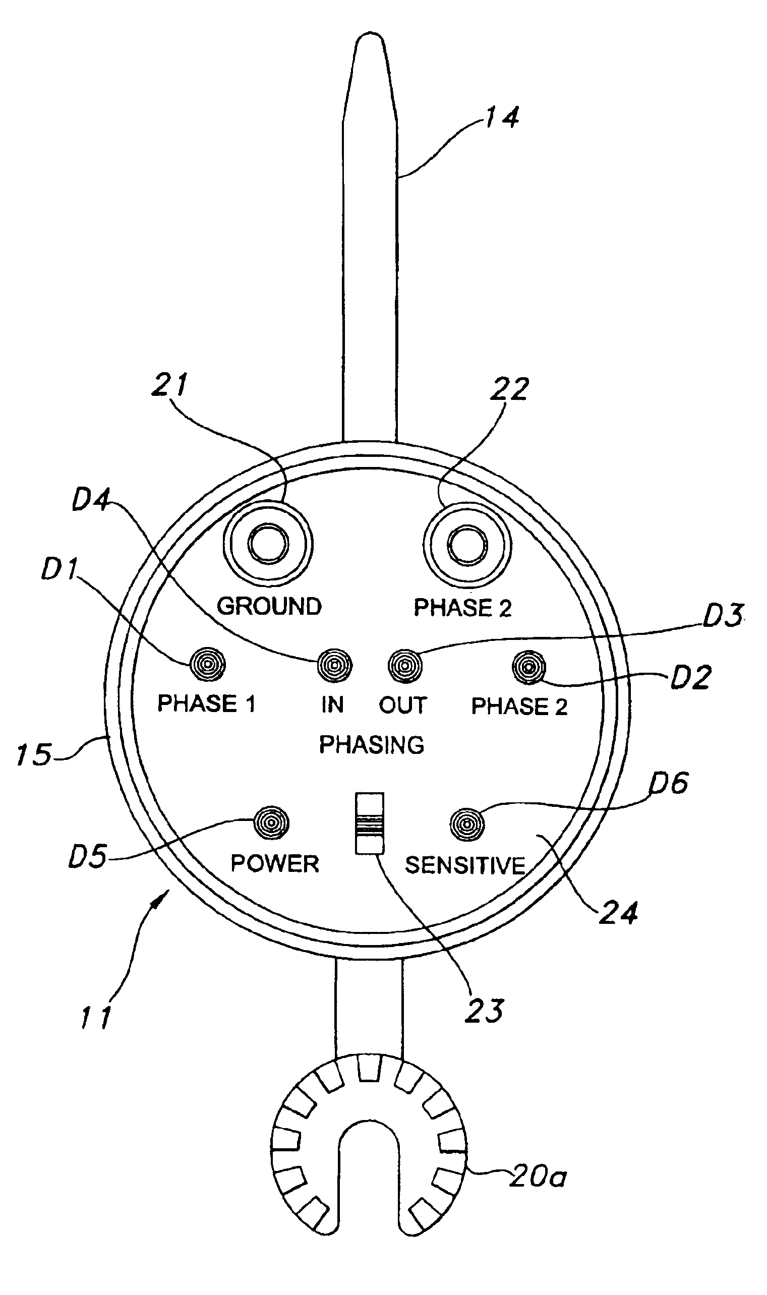
[0016]Referring now to FIG. 1, a capacitive test point voltage and phasing detector 10 is shown in use in an environment which is shown schematically. The capacitive test point voltage and phasing detector 10 generally includes a first detector member 11 and a second detector member 12 which are in electrical communication with each other by a phase 2 lead 13, which is merely a wire. Preferably the first detector member 11 includes a longitudinally extended first probe 14 having a pointed upper end 14a and a lower end 14b. The first detector member 11 also includes a circular shaped module 15 connected between the upper and the lower end of the first probe 14. The first probe 14 is configured to engage with a first capacitive point 16 at the pointed upper end 14a to take a voltage reading. The first probe 14 is electrically coupled to the module 15. Moreover, a first universal adapter 16 is connected to the lower end of the first probe 14 to facilitate the attachment of the first de...


PUM


Abstract

Method and apparatus for accurately determining the presence of voltage at capacitive test points and for determining the phase angle relationship between two capacitive points. The detection of the presence of the voltage at the capacitive test points is independent of the voltage range in the systems, independent of the contamination or defects that may occur in the capacitive test point systems. The phase angle relationship is determined based on the actual phase angle difference between the voltage waveforms at the capacitive test points independent of the capacitive divider ratio difference and the capacitive test point voltage accuracy.

Description

CROSS-REFERENCE TO RELATED APPLICATIONS[0001]This application is a divisional of U.S. patent application Ser. No. 10 / 033,118, filed Oct. 26, 2001 U.S. Pat. No. 6,677,741.FIELD OF THE INVENTION[0002]The present invention relates generally to a method and apparatus for determining the presence of voltage and determining the phase relationship between capacitive test points. More specifically, the present invention is directed to determining the presence of voltage at capacitive test points and measuring the actual phase angle difference between the two capacitive test points in order to determine the phase relationship between the two capacitive test points.BACKGROUND OF THE INVENTION[0003]In the past, the phase relationship between two capacitive test points was determined based on voltage measurements at the capacitive test points. Ideally, the voltage difference between the two capacitive test points would be zero if in phase and significantly larger if out of phase. However, due t...

Claims


Application Information

Patent Timeline
Patent Type & Authority Patents(United States)
IPC IPC(8): G01R25/00G01R19/155
CPCG01R25/00
Inventor TAYLOR, TIMOTHY R.
Owner THOMAS & BETTS INT INC