
Method and device for operating a steam power plant, in particular in the part-load range

a technology for steam power plants and parts, applied in the direction of engine starters, liquid degasification, separation processes, etc., can solve the problems of considerable efficiency loss, disadvantages of related art, and the inability to overcome the loss, so as to improve the regulating behavior of steam turbines.

Inactive Publication Date: 2005-07-12
SIEMENS AG
View PDF9 Cites 5 Cited by
  • Summary
  • Abstract
  • Description
  • Claims
  • Application Information

AI Technical Summary

Benefits of technology

[0015]Particularly in the part-load range, continuous throttling of the turbine valves and the efficiency loss associated with this can be avoided when care is taken to ensure that, in particular, the stresses which occur in the material of the steam-carrying component do not become too great, but at the same time the upper mechanical load limit of the material of the steam-carrying component is utilized. The method therefore dispenses, inter alia, with too great a safety margin of the mechanical stresses actually prevailing in the material of the steam-carrying component from the maximum permissible mechanical stresses, in order thereby, in particular, to avoid too great an efficiency loss.
[0030]In this case, for example, the required limit steam pressure desired value and its time profile can be determined arithmetically by the mathematical model of the steam-carrying component, in that, for example, in the simulation calculation, starting from the measured internal pressure of the steam-carrying component, this current value of the internal pressure is increased in steps purely arithmetically, until the (initially theoretical) reference stress occurring in this case reaches or at least approaches the value of the material limit stress. The limit steam pressure desired value determined in this way can then be set so that no damage to the steam-carrying component need be feared.

Problems solved by technology

At the same time, in particular, the disadvantages from the related art, such as for example, the considerable efficiency loss occurring in this case, are to be overcome.

Method used


Image

  • Method and device for operating a steam power plant, in particular in the part-load range
  • Method and device for operating a steam power plant, in particular in the part-load range

Examples


Embodiment Construction

[0046]Reference will now be made in detail to the preferred embodiments of the present invention, examples of which are illustrated in the accompanying drawings, wherein like reference numerals refer to like elements throughout.

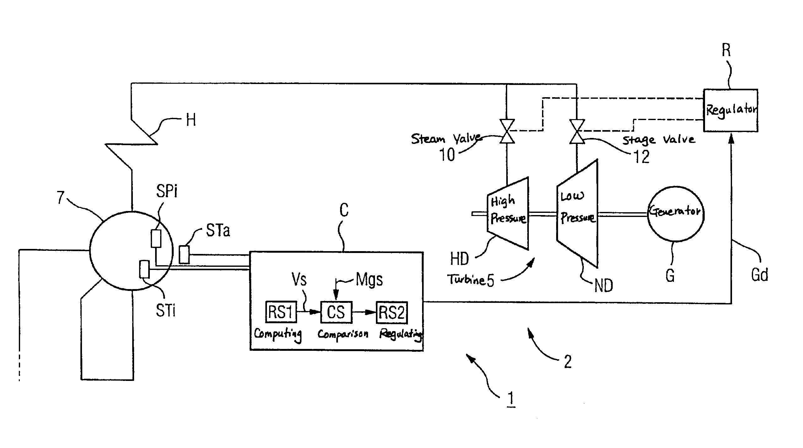
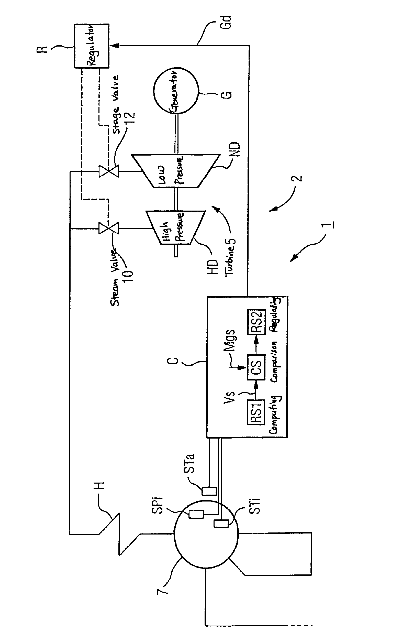
[0047]The figure shows a steam power plant 1 which comprises a steam turbine 5 and at least one steam-carrying component 7. The latter is designed, in the present exemplary embodiment, as a steam separation drum.

[0048]No details of steam generation are depicted in the diagrammatic illustration of the figure, and, in particular, a detailed illustration of steam generation with a steam boiler and with further components has been dispensed with.

[0049]The generation of fresh steam for the steam turbine 5 is indicated by a heating surface H, by which a flow medium is heated by the action of, for example, hot gas and it can be delivered to the steam turbine 5 as fresh steam.

[0050]The steam turbine 5 has two turbine stages with a different operating pressure, to be ...


PUM

PropertyMeasurementUnit
pressureaaaaaaaaaa
temperatureaaaaaaaaaa
mechanical stressaaaaaaaaaa

Abstract

It is proposed that, during the operation of a steam turbine of a steam power plant, the internal pressure and also the internal temperature and, in the region outside it, the external temperature be determined in at least one steam-carrying component. As a result of a change in the operating state, in particular in the event of a load change, then, the abovementioned values vary, so that, under some circumstances, the mechanical stresses which in this case act on the steam-carrying component become unacceptably high. Consequently, a spatial temperature distribution and a reference stress of the steam-carrying component are determined from the abovementioned values and compared with a material limit stress. If the reference stress is greater than the material limit stress, a limit steam pressure desired value is determined, and at least one steam valve is set in such a way that the steam pressure on the steam-carrying component corresponds approximately to this limit steam pressure desired value. By the method according to the invention, an automatic reduction in the throttling is obtained, so that the efficiency of the steam power plant, in particular in the part-load range, is increased. A device according to the invention serves for carrying out the method according to the invention.

Description

CROSS REFERENCE TO RELATED APPLICATIONS[0001]This application is based on and hereby claims priority to European Application No. 02011279.3 filed on May 22, 2002, the contents of which are hereby incorporated by reference.BACKGROUND OF THE INVENTION[0002]Plants for the generation of electrical energy, in particular steam power stations, are conventionally designed for operating with a specific power output, the nominal power output, so that, when the plant is operating with this power output, optimum operating conditions of the numerous plant components are obtained, for example in terms of wear, frictional forces and frictional losses which occur, the generation of noise, exhaust gas behavior and efficiency.[0003]In known power plants, there is often the problem that demand-related load changes cannot be carried out as quickly as desired while the power plant is in operation. For example, the speed of load change of steam power stations is restricted by the temperature variations o...

Claims


Application Information

Patent Timeline
Patent Type & Authority Patents(United States)
IPC IPC(8): F01D19/00F01D19/02F01D17/08F01K13/00F01K13/02F01D17/00
CPCF01D17/08F01D19/02F01K13/02F05D2270/303F05D2270/301
Inventor WOLF, THORSTEN
Owner SIEMENS AG
Learn More