Multi-reservoir pressure control system

a pressure control system and multi-reservoir technology, applied in flow control, diaphragms, electrolysis, etc., can solve the problems of more difficult quality control, inaccurate and repeatable specific flow accuracy, and inability to accurately apply electrical fields in some instances, so as to achieve accurate and reliable assays, the effect of sufficient oscillation

Inactive Publication Date: 2005-07-12
CAPLIPER LIFE SCI INC
View PDF30 Cites 275 Cited by
  • Summary
  • Abstract
  • Description
  • Claims
  • Application Information

AI Technical Summary

Benefits of technology

[0012]The present invention generally provides improved microfluidic devices, systems, and methods. The devices and systems of the invention generally allow flexible and selective transportation of fluids within microfluidic channels of a microfluidic network by applying, controlling, and varying pressures at a plurality of reservoirs or ports. By modeling the microfluidic network as a series of nodes (including the reservoirs, channel intersections, and the like) connected together by channel segments, and by determining the flow resistance characteristics of the channel segments, the fluid flows through the channel segments resulting from a given pressure configuration at the reservoirs can be determined. Reservoir pressures to effect a desired flow profile may also be calculated using the network model. A simple multi-reservoir pressure modulator and pressure controller system can optionally be used in conjunction with electrokinetic or other fluid transport mechanisms. The invention also provides techniques to avoid fluid mixture degradation within a microfluidic channel by maintaining sufficient oscillation to avoid separation of the fluid mixture when no gross movement of the fluid is desired. Microfluidic systems and methods having viscometers or other flow sensors are particularly useful for determining pressures so as to hydrodynamically induce a desire to flow in response to a measured flow within a microfluidic channel. Regardless of the mechanism used to effect movement of fluids within a microfluidic network, the techniques of the present invention may be used to provide feedback on the actual flow and / or network system characteristics, allowing (for example) more accurate, stable and reliable assays.
[0023]The methods of the present invention are particularly well suited for precisely combining selected fluids within a microfluidic network, such as for multiport dilution in which concentrations of first and second fluids from first and second reservoirs can be combined at different concentrations.
[0026]While analysis of the microfluidic network based on the known channel geometry can significantly facilitate calculation of pressures to be applied for generation of a desired hydrodynamic flow, work in connection with the present invention has shown that the complex nature of the flows within a microfluidic channel can make calculation of effective fluid viscosity within a microfluidic network highly problematic. Specifically, the flows within a single channel of a microfluidic network may include differing dilutions of test fluids separated by a plurality of different buffering solutions, and the like. To over come this complication, the invention often makes use of viscometers and other flow sensing systems to determine actual flow characteristics from a known microfluidic driving force. Based on these measurements, a desired flow may then be generated hydrodynamically by adjusting the appropriate reservoir pressures.
[0033]The pressure transient may conveniently be applied by spontaneous injection of an introduced fluid into an injection channel of the microfluidic network. Such spontaneous injection may draw the introduced fluid into the injection channel using capillary forces between the injection channel and the introduced fluid.

Problems solved by technology

For example, while electrokinetic material transport systems provide many benefits in the micro-scale movement, mixing, and aliquoting of fluids, the application of electrical fields can have detrimental effects in some instances.
Regardless of the mechanism used to effect movement of fluid and other materials within a microfluidic channel network, accuracy and repeatability of specific flows can be problematic.
There may be variations in, for example, electroosmotic flow between two chips having similar designs, and even between different operations run on a single chip at different times. Quality control can be more challenging in light of this variability, as accurate control over microfluidic flows in applications such as high throughput screening would benefit significantly from stable and reliable assays.

Method used


Image

  • Multi-reservoir pressure control system
  • Multi-reservoir pressure control system
  • Multi-reservoir pressure control system

Examples


Embodiment Construction

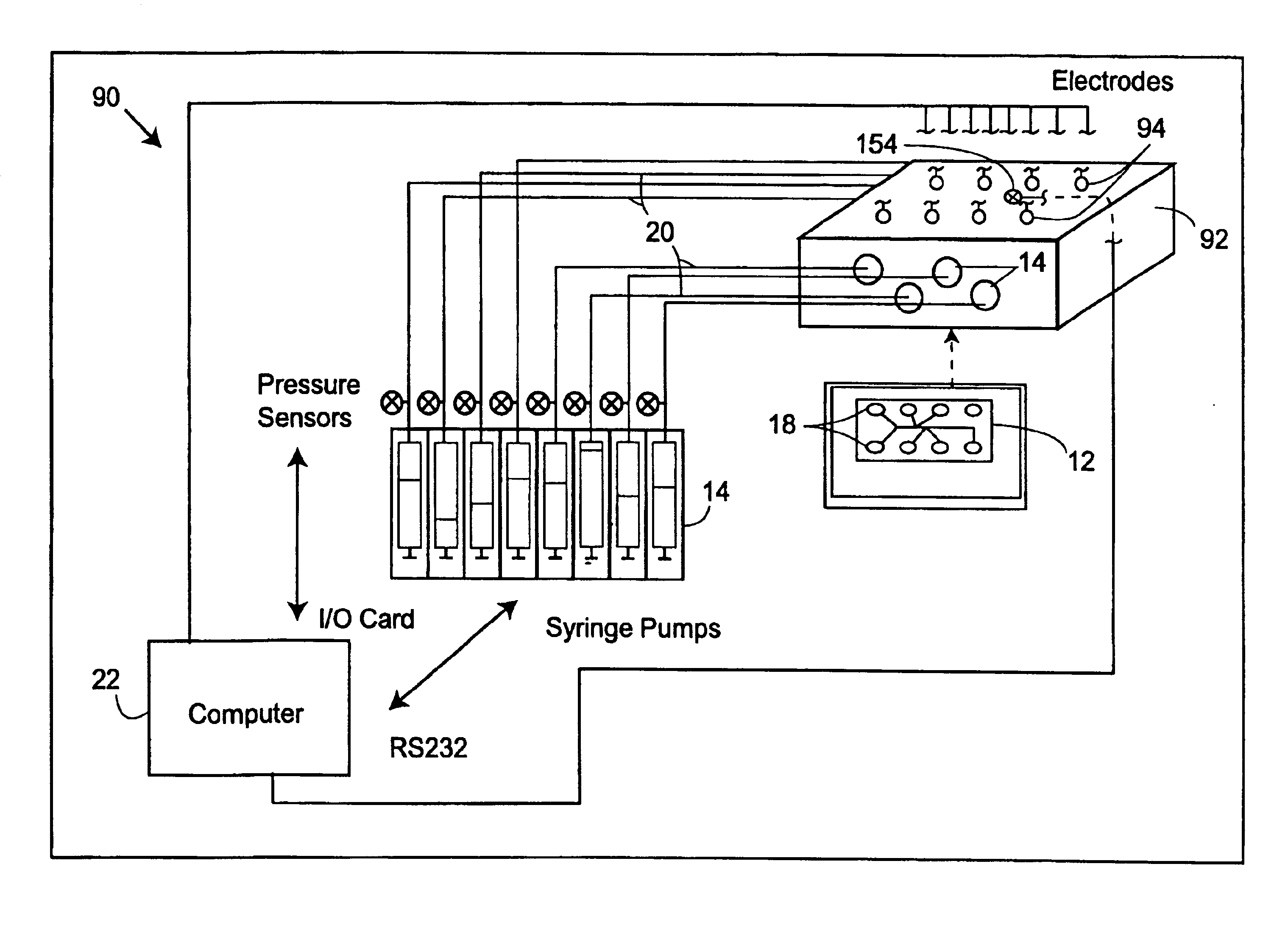
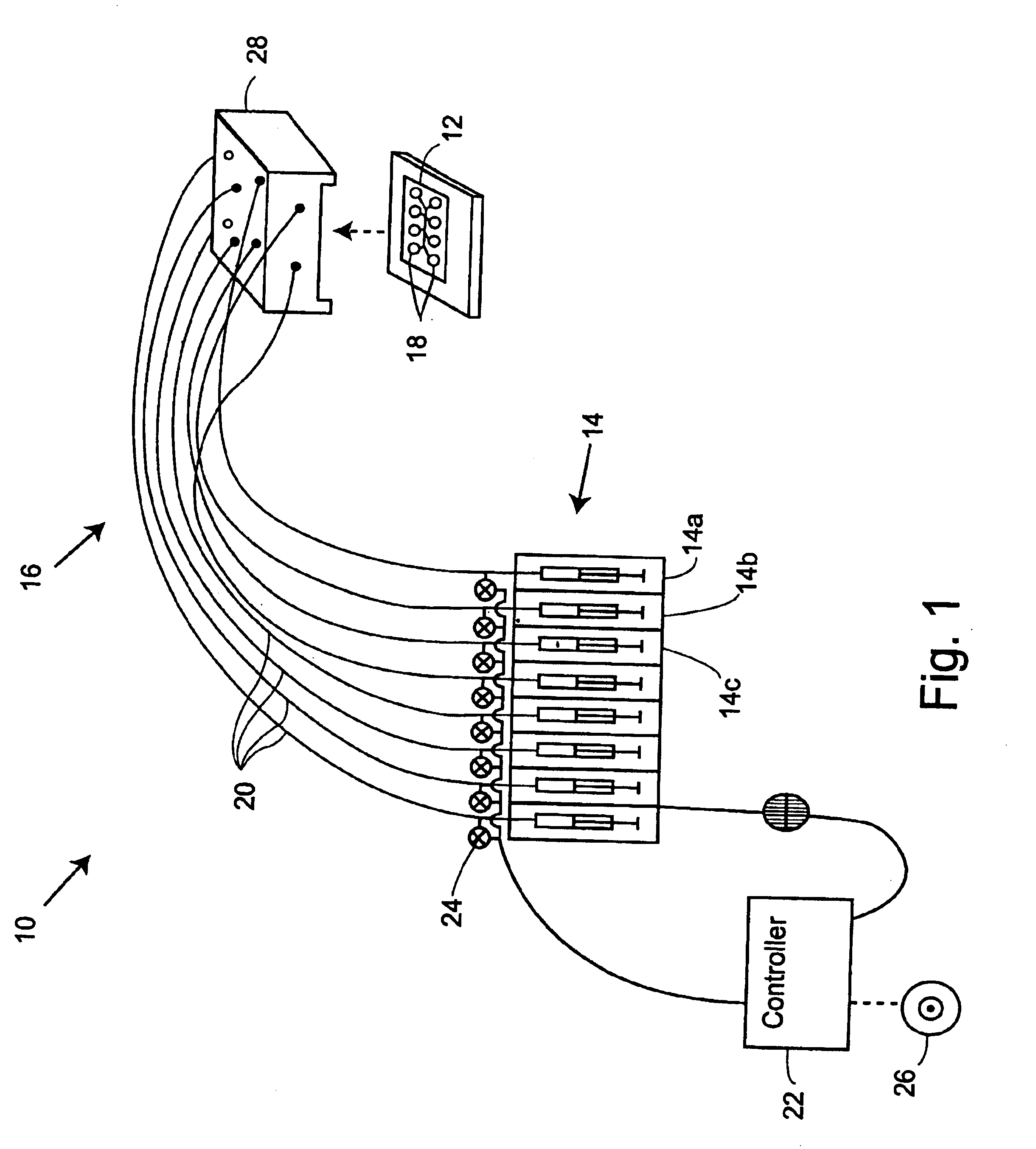
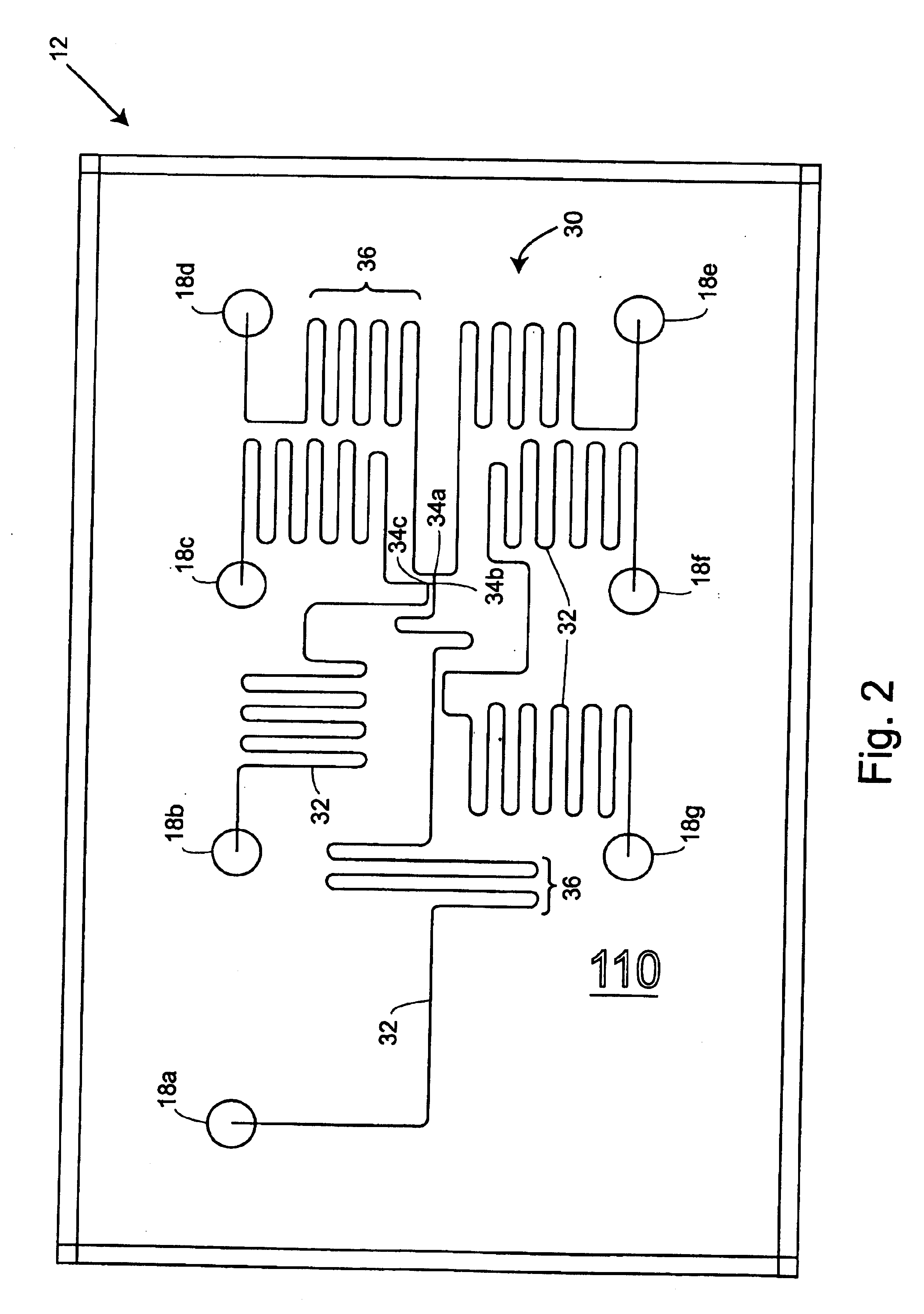
[0059]The present invention generally makes use of a multi-reservoir pressure controller coupled to a plurality of independently variable pressure modulators to effect movement of fluids within microfluidic networks. By selectively controlling and changing the pressure applied to the reservoirs of a microfluidic device, hydrodynamic flow at very low flow rates may be accurately controlled within intersecting microfluidic channels. Such pressure-induced flows can help to decrease (or entirely avoid) any detrimental effects of the electrical fields associated with electrokinetic transportation methods, such as sample bias, cell perforation, electroporation, and the like. Additionally, such pressure-induced microfluidic flows may, through proper chip design, reduce flow variabilities as compared to electrokinetic techniques through the use of pressure differentials (and / or channel resistances that are significantly greater than flow variations induced by secondary effects, such as infl...


PUM

PropertyMeasurementUnit
flow ratesaaaaaaaaaa

Abstract

Improved microfluidic devices, systems, and methods allow selective transportation of fluids within microfluidic channels of a microfluidic network by applying, controlling, and varying pressures at a plurality of reservoirs. Modeling the microfluidic network as a series of nodes connected together by channel segments and determining the flow resistance characteristics of the channel segments may allow calculation of fluid flows through the channel segments resulting from a given pressure configuration at the reservoirs. To effect a desired flow within a particular channel or series of channels, reservoir pressures may be identified using the network model. Viscometers or other flow sensors may measure flow characteristics within the channels, and the measured flow characteristics can be used to calculate pressures to generate a desired flow. Multi-reservoir pressure modulator and pressure controller systems can optionally be used in conjunction with electrokinetic or other fluid transport mechanisms.

Description

CROSS-REFERENCES TO RELATED APPLICATIONS[0001]The subject matter of the present application is related to that of U.S. Provisional Patent Application No. 60 / 184,390 filed Feb. 23, 2000, and to that of Provisional Patent Application No. 60 / 216,793 filed on Jul. 7, 2000, the full disclosures of which are incorporated herein by reference.BACKGROUND OF THE INVENTION[0002]The present invention is generally related to analytical tools for the biological and chemical sciences, and in particular, provides microfluidic devices, systems, and methods for selectively transporting fluids within microfluidic channels of a microfluidic network, often using a plurality of selectively variable pressures.[0003]Microfluidic systems are now in use for the acquisition of chemical and biological information. These microfluidic systems are often fabricated using techniques commonly associated with the semiconductor electronics industry, such as photolithography, wet chemical etching, and the like. As used...

Claims


Application Information

Patent Timeline
Patent Type & Authority Patents(United States)
IPC IPC(8): B01L3/00G01N27/447G05D7/06G01N11/00G01N11/08G01N35/10G01N11/04B01L9/00G01N27/06G01N35/08G01N37/00
CPCB01L3/502715B01L3/50273B01L3/502738B01L3/502746B01L9/527G01N27/44791G05D7/0694B01L2200/025B01L2200/027B01L2200/146B01L2300/0816B01L2300/0867B01L2400/0415B01L2400/0487B01L2400/082G01N11/08G01N2035/1044Y10T137/86131Y10T137/2076Y10T137/218
Inventor CHIEN, RING-LINGPARCE, J. WALLACECHOW, ANDREA W.KOPF-SILL, ANNE
Owner CAPLIPER LIFE SCI INC
Why Eureka
Try Eureka