Wireless communication terminal and voltage controlled oscillator therefor

a wireless communication terminal and voltage control technology, applied in the direction of oscillator generators, angle modulation details, pulse automatic control, etc., can solve the problems of reducing the gain margin, and reducing the cost of vco implementation, so as to improve the phase noise, widen the bandwidth, and improve the effect of phase nois

Inactive Publication Date: 2004-11-11
MOTOROLA SOLUTIONS ISRAEL
View PDF6 Cites 8 Cited by
  • Summary
  • Abstract
  • Description
  • Claims
  • Application Information

AI Technical Summary

Benefits of technology

0019] The provision of an additional (second), variable, tuning capacitance, located adjacent to the resonator enables a VCO to operate over a wider bandwidth with the same tuning voltages, say around 15% of the VCO's centre frequency. This is achieved, effectively, due to the use of gain margin tuning applied to the resonator and second variable capacitor of the VCO circuit. In particular, the provision of an additional (second) variable capacitor located adjacent to the resonator provides an increase in loaded-Q at high tuning voltages, i.e. it provides better phase noise at those frequencies. It also provides an increase in gain margin at low frequencies, i.e. it insures a minimum gain margin to provide sufficient oscillation, thereby providing greater start-up confidence at low tuning voltages. In this manner, the present invention solves the problem of lack of gain margin in a traditional Colpitts VCO configuration that would have resulted in oscillation start-up problems in the lower tuning voltage range.

Problems solved by technology

Developing a single wideband VCO to operate across the desired frequency range saves cost and space, when compared to the alternative solution of designing two separate VCO circuits.
However, the implementation of a `wideband` VCO is more complex.
Furthermore, the inventors of the present invention have recognised that a significant disadvantage with such wideband VCO designs is that VCO phase noise degrades over the frequency band.
This problem is exacerbated as the VCO bandwidth increases.
The increased capacitance change will increase the variable capacitance losses as well.
This, in turn, leads to oscillation start up problems, particularly in a traditional Colpitts VCO configuration.

Method used


Image

  • Wireless communication terminal and voltage controlled oscillator therefor
  • Wireless communication terminal and voltage controlled oscillator therefor
  • Wireless communication terminal and voltage controlled oscillator therefor

Examples


Embodiment Construction

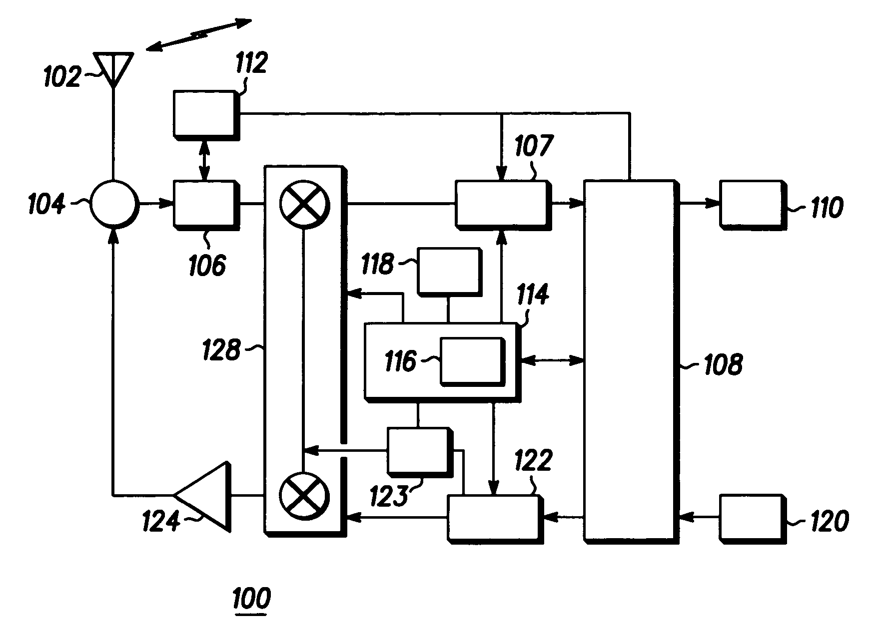
[0026] A block diagram of a wireless subscriber communication unit (often termed mobile station (MS)) 100 is shown in FIG. 1. The MS 100 is adapted to support the inventive concepts of the preferred embodiments of the present invention. The MS 100 contains an antenna 102 preferably coupled to a duplex filter or antenna switch 104 that provides isolation between receive and transmit chains within the MS 100.

[0027] The receiver chain includes receiver front-end circuitry 106 (effectively providing reception, amplification and filtering of the received signal). The received signal is input to a frequency conversion circuit 128 that receives a reference oscillator signal from the frequency generation circuit 123. The frequency conversion circuit 128 preferably comprises mixing and amplifier elements (not shown), as known in the art. The frequency conversion circuit 128 is serially coupled to a signal processing function (generally realised by a digital signal processor (DSP)) 108 via a ...


PUM


Abstract

A wireless communication unit (100) comprises a voltage controlled oscillator (123) having an active device (450) operably coupled to a first variable capacitance (425) to provide a variable capacitance value based on an applied steering line voltage, and a feedback network comprising a resonator (475), operably coupled to an output of the active device, for feeding power back to an input of the active device to sustain oscillations (123). Notably, a second variable capacitance is operably coupled to receive a control voltage from the steering line (405) and located between the resonator (475) and the active device (450).

Description

[0001] This invention relates to a wireless commnunication terminal and a voltage controlled oscillator therefor. The invention is applicable to, but not limited to, a voltage controlled oscillator (VCO) for generating radio frequencies across a wide frequency range and / or over a number of distinct frequency bands.[0002] Wireless subscriber communication units, for example those operating in a cellular telephone system such as the Global System for Mobile communications (GSM) or operating on a private mobile radio system such as a TErrestrial Trunked RAdio (TETRA) communication system, use oscillator circuits to generate the radio frequency signals.[0003] An oscillator circuit has two primary functions:[0004] (i) An active device, such as a transistor, to produce power gain; and[0005] (ii) A feedback network, routeing a sufficient amount of the active device's output signal to an input of the active device, to sustain oscillations. In effect, the component values of the feedback net...

Claims


Application Information

Patent Timeline
Patent Type & Authority Applications(United States)
IPC IPC(8): H03B5/12
CPCH03B5/1203H03B5/1231H03B5/1243
Inventor CORSE, NIRNIR, SHAYROZENTAL, MARK
Owner MOTOROLA SOLUTIONS ISRAEL
Why Eureka
Try Eureka