Method to shear a strip during the casting step

Inactive Publication Date: 2005-07-12
DANIELI & C OFF MEC SPA
View PDF5 Cites 2 Cited by
  • Summary
  • Abstract
  • Description
  • Claims
  • Application Information

AI Technical Summary

Benefits of technology

[0029]In another embodiment of the invention, after the increase in speed which creates the inclusion of liquid metal downstream of the kissing point, the casting speed is kept at said increased value. In this case, once the inclusion has been formed with a con

Problems solved by technology

It is known that the initial segment of strip, produced in non-stationary conditions, has an irregular conformation which could make it difficult for the strip to enter the pinch-roll or possible rolling stands, which usually have a limited aperture.
This irregular conformation, moreover, has a quality which is unacceptable from the production point of view.
The final segment of the cast strip is also produced in non-stationary conditi

Method used


Image

  • Method to shear a strip during the casting step
  • Method to shear a strip during the casting step
  • Method to shear a strip during the casting step

Examples


Embodiment Construction

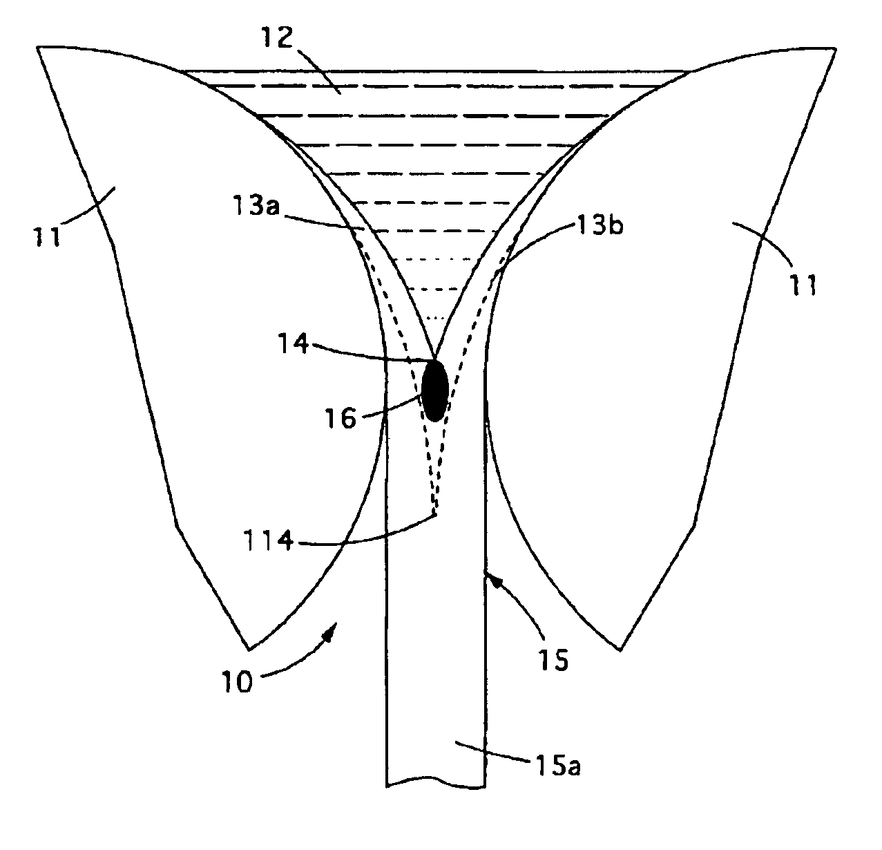
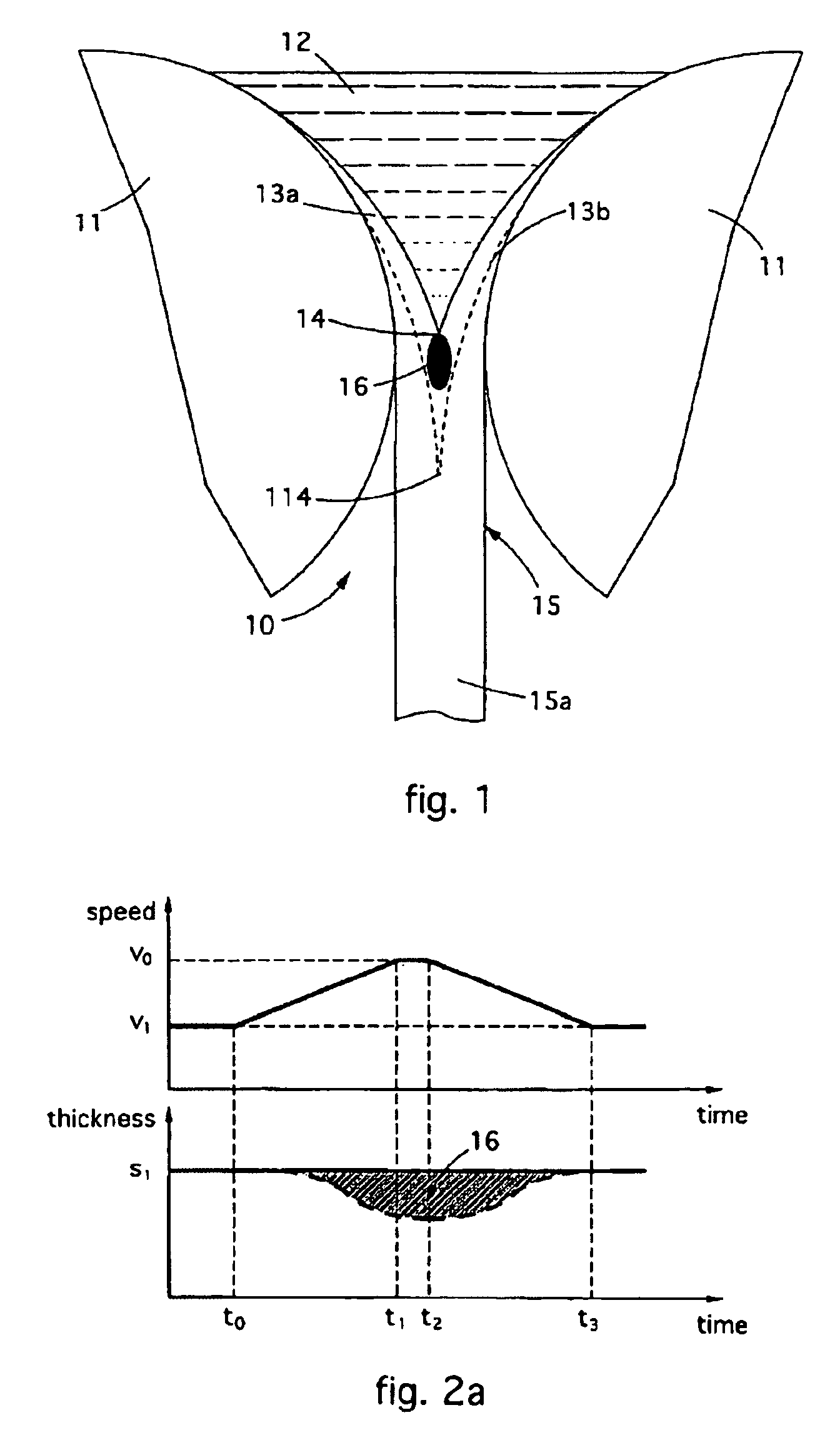
[0034]With reference to the attached drawings, and particularly to FIG. 1, number 10 denotes generally and schematically a continuous casting machine with two rollers 11, wherein molten metal 12 is discharged by suitable means (not shown here) and cast through a gap with an adjustable amplitude defined by the reciprocally facing surfaces of said rollers 11.

[0035]Downstream of the rollers 11 there are usual, and not shown here, guide and extraction systems, normally with rollers, associated with cooling means.

[0036]The rollers 11, in known manner, are cooled at least on the surface and the contact between the molten metal 12 and these cooled surfaces causes the formation of two at least partly solidified half-skins 13a, 13b, which preferentially join in correspondence with the kissing point 14, corresponding to the position of minimum distance between the two rollers 11.

[0037]At outlet from the rollers 11, thanks also to the cooling systems located downstream, a solidified strip 15 i...


PUM

PropertyMeasurementUnit
Timeaaaaaaaaaa
Timeaaaaaaaaaa
Timeaaaaaaaaaa

Abstract

Method to shear a strip during the casting step, wherein the casting speed is increased, with respect to a speed of a stationary regime, maintaining the thickness of said cast strip constant to the value corresponding to the speed of a stationary regime, in order to determine the formation of a |liquid core which determines the re-melting of the adjacent skin and the breakage of the strip due to the weight of the part of the strip located under the liquid core.

Description

FIELD OF THE INVENTION[0001]The invention concerns a method to shear a metal strip during the production thereof by means of continuous casting from the liquid metal.[0002]The invention can be used in particular to remove a leading end segment of a desired length of a strip emerging from a continuous casting machine with two rollers, or, at the end of casting, to eliminate the terminal segment cast during the final transitory period.[0003]The invention can also be used in any step whatsoever of the casting, for example in emergency conditions to interrupt cleanly the strip cast before discharging the liquid metal contained in the casting machine, or to separate the production of two strips of different thickness, or again when the machine is operating in stationary conditions and it is desired to separate segments of strip for production reasons.[0004]To be more exact, the invention concerns a shearing method by means of which it is possible to separate a desired segment of strip du...

Claims


Application Information

Patent Timeline
IPC IPC(8): B22D11/06B22D11/126B22D11/12
CPCB22D11/0622B22D11/126
Inventor POLONI, ALFREDOKAPAJ, NUREDIN
Owner DANIELI & C OFF MEC SPA
Why Eureka
Try Eureka