Power generation system and method

a power generation system and hybrid technology, applied in hybrid vehicles, machines/engines, cell components, etc., can solve the problems of failure or degraded components, uncertain market-based economics of alternative fuels or new power train systems, and the emission of “ultra low emission” certified vehicles in limited extreme ambient and operating conditions

Inactive Publication Date: 2005-07-12
DELPHI TECH INC
View PDF23 Cites 148 Cited by
  • Summary
  • Abstract
  • Description
  • Claims
  • Application Information

AI Technical Summary

Benefits of technology

[0010]The method comprises supplying at least a first portion of fuel and a first portion of air to an engine, wherein said engine is configured to produce a rich engine exhaust; reacting said first portion of fuel and said first portion of air in said engine to produce a hydrogen rich engine exhaust; introducing said hydrogen rich engine exhaust to a fuel intake of a SOFC; introducing a second portion of air to an air intake of said SOFC; and ionizing oxygen in the second portion of air such that the ionized oxygen migrates to the fuel side of the SOFC where it reacts with said hydrogen rich engine exhaust to produce a SOFC effluent. The resulting system exhaust has negligible to zero amounts of nitric oxides, hydrocarbons, carbon monoxide, and particulates, due to some reduction within SOFC, recirculation of SOFC effluent through the system and / or passage of SOFC effluent through a catalytic converter.

Problems solved by technology

This has certainly reduced the environmental differential between optimized conventional and alternative fuel vehicle systems.
However, many technical challenges remain to make the conventionally fueled internal combustion engine a nearly zero emission system having the efficiency necessary to make the vehicle commercially viable.
Unfortunately, the market-based economics of alternative fuels or new power train systems are uncertain in the short to mid-term.
Yet, even an “ultra low emission” certified vehicle can emit high emissions in limited extreme ambient and operating conditions or with failed or degraded components.

Method used


Image

  • Power generation system and method
  • Power generation system and method
  • Power generation system and method

Examples


Embodiment Construction

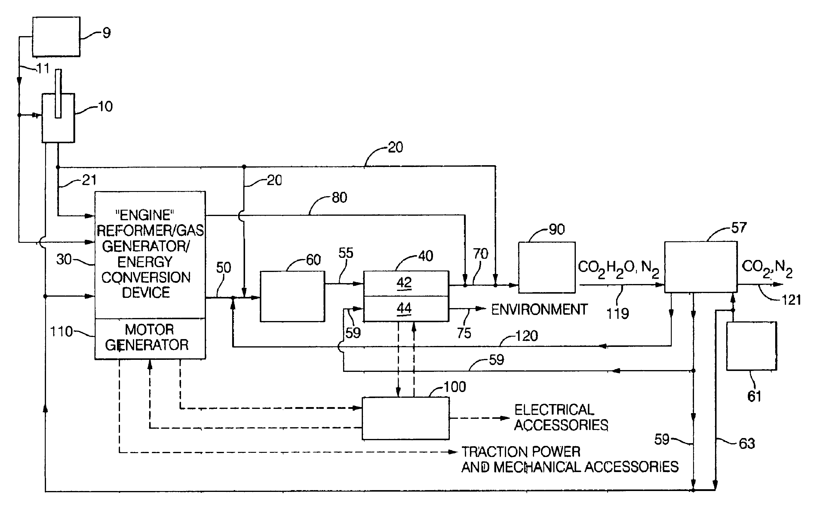
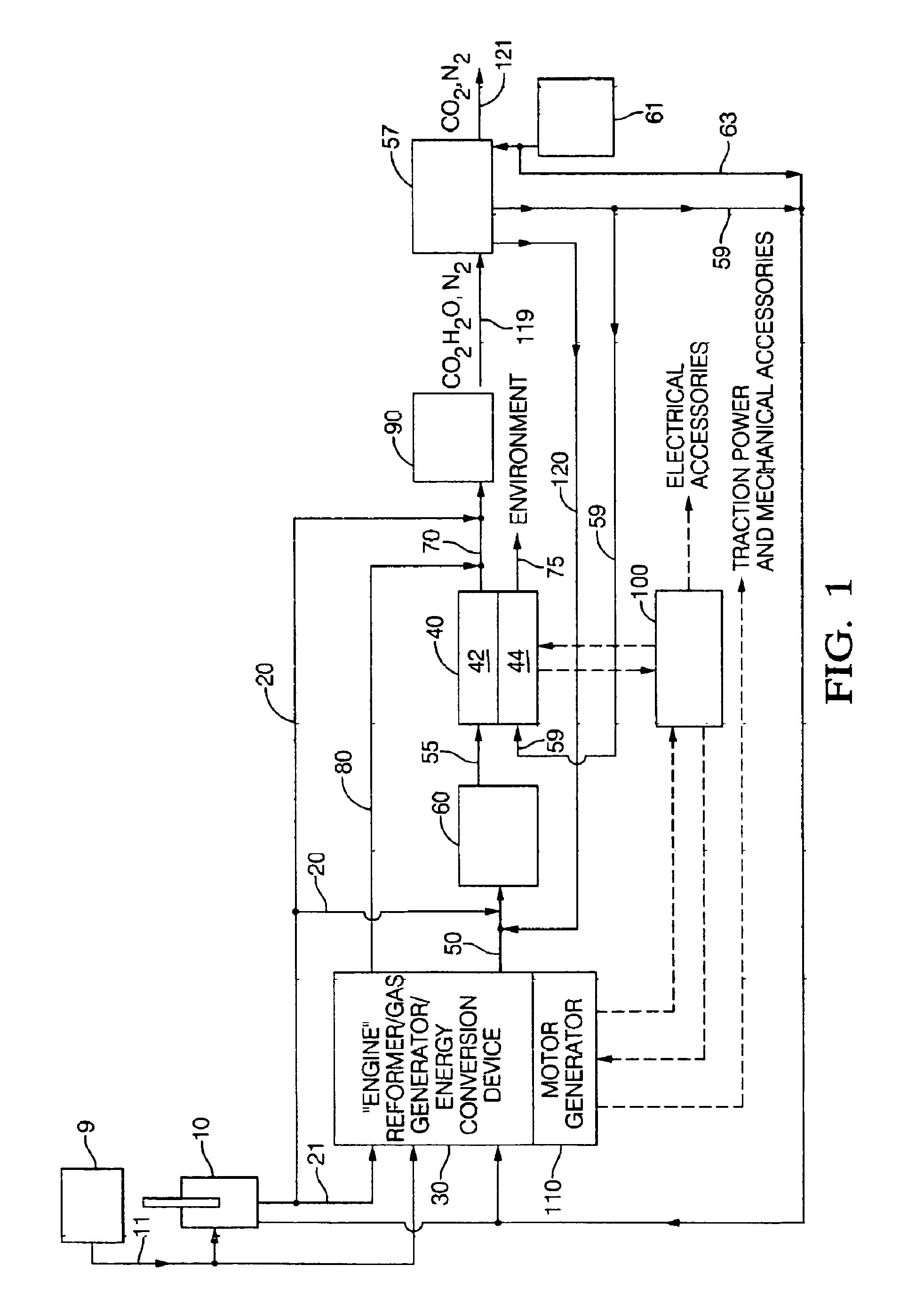
[0021]The present system and method relate to an engine configured and operated to produce a hydrogen rich engine exhaust and to oxygen enrichment devices to further optimize production of hydrogen rich engine exhaust. The present hydrogen rich exhaust engines include, but are not limited to, a free piston gas generator with rich homogenous charge compression ignition, an oxygen generator and rich internal combustion engine cylinder system, and a rich inlet turbo-generator system with exhaust heat recovery. Oxygen enrichment devices include, but are not limited to, pressure swing absorption (PSA) with oxygen selective materials, oxygen separators such as an SOFC oxygen separator and an oxygen separator utilizing a ceramic membrane and differential pressure to drive oxygen across the membrane.

[0022]The present invention further relates to a power generation system and method employing the present hydrogen rich exhaust engines and oxygen enrichment devices, and especially relates to a...


PUM

PropertyMeasurementUnit
operational temperaturesaaaaaaaaaa
temperaturesaaaaaaaaaa

Abstract

A power generation system and method providing an engine configured to produce hydrogen rich reformate to feed a solid oxide fuel cell includes an engine having an intake and an exhaust; an air supply in fluid communication with the engine intake; a fuel supply in fluid communication with the engine intake; at least one solid oxide fuel cell having an air intake in fluid communication with an air supply, a fuel intake in fluid communication with the engine exhaust, a solid oxide fuel cell effluent and an air effluent. Engines include a free piston gas generator with rich homogenous charge compression, a rich internal combustion engine cylinder system with an oxygen generator, and a rich inlet turbo-generator system with exhaust heat recovery. Oxygen enrichment devices to enhance production of hydrogen rich engine exhaust include pressure swing absorption with oxygen selective materials, and oxygen separators such as an solid oxide fuel cell oxygen separator and a ceramic membrane oxygen separator.

Description

CROSS-REFERENCE TO RELATED APPLICATIONS[0001]The present application is a divisional application of and claims priority to U.S. Pat. No. 6,609,582, application Ser. No. 09 / 294,679 of Jean Joseph Botti, et al., filed Apr. 19, 1999, entitled “Power Generation System and Method,” which is hereby incorporated by reference herein in its entirety.TECHNICAL FIELD[0002]The present invention relates to a power generation system and method, and especially relates to a hybrid electric powertrain having an engine configured to produce reformate to feed a solid oxide fuel cell.BACKGROUND OF THE INVENTION[0003]Alternative transportation fuels have been represented as enablers to reduce toxic emissions in comparison to those generated by conventional fuels. At the same time, tighter emission standards and significant innovation in catalyst formulations and engine controls has led to dramatic improvements in the low emission performance and robustness of gasoline and diesel engine systems. This has...

Claims


Application Information

Patent Timeline
Patent Type & Authority Patents(United States)
IPC IPC(8): B60K6/04B60K6/00F02B1/12F02B1/00H01M8/12H01M8/04H01M8/06B60K6/24B60K6/26B60K6/32B60K6/46B60K6/48
CPCB60K6/24B60K6/26B60K6/32B60K6/46B60K6/48F02B1/12H01M8/04089H01M8/0612H01M8/1206B60W2710/06H01M8/04022H01M2008/1293H01M2250/20H01M2300/0074Y02E60/521Y02E60/525Y02T10/6217Y02T10/6221Y02T10/6295Y02T90/32Y02T90/34Y10S903/905Y10S903/908Y10S123/12Y10S903/906Y10S903/944H01M8/1231Y02E60/50Y02T10/62Y02T90/40
Inventor BOTTI, JEAN JOSEPHGRIEVE, MALCOLM JAMESMILLER, CARL ELMER
Owner DELPHI TECH INC
Why Eureka
Try Eureka