Electric braking apparatus
a technology of electric brakes and calipers, which is applied in the direction of brake systems, friction linings, transportation and packaging, etc., can solve the problems of mechanical brake operating mechanisms that may not be suited to all vehicles, electric brakes cannot operate, and calipers are elongated so as to achieve the effect of not enlarging the length of the caliper in the axial direction
- Summary
- Abstract
- Description
- Claims
- Application Information
AI Technical Summary
Benefits of technology
Problems solved by technology
Method used
Image
Examples
first embodiment
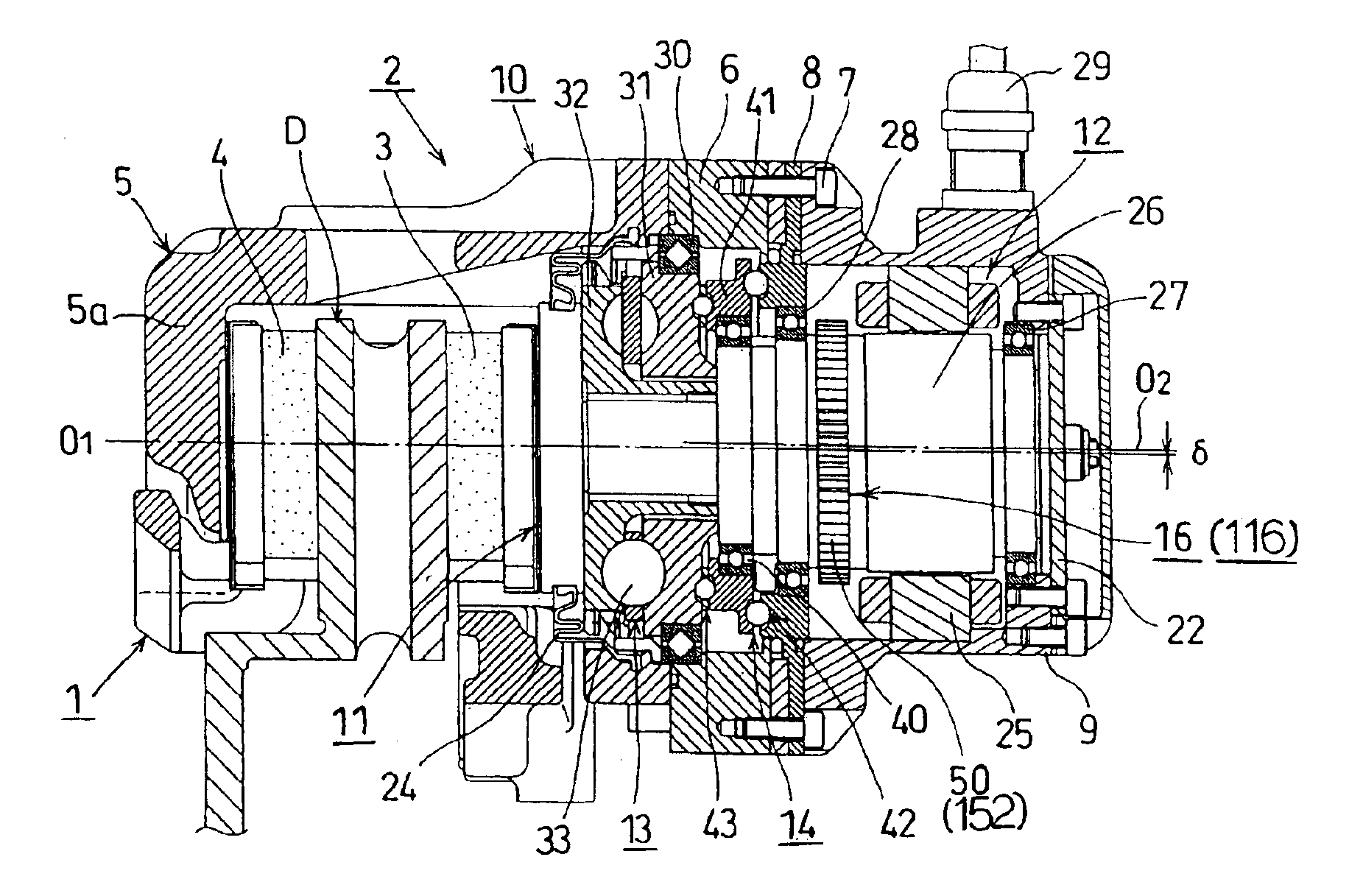
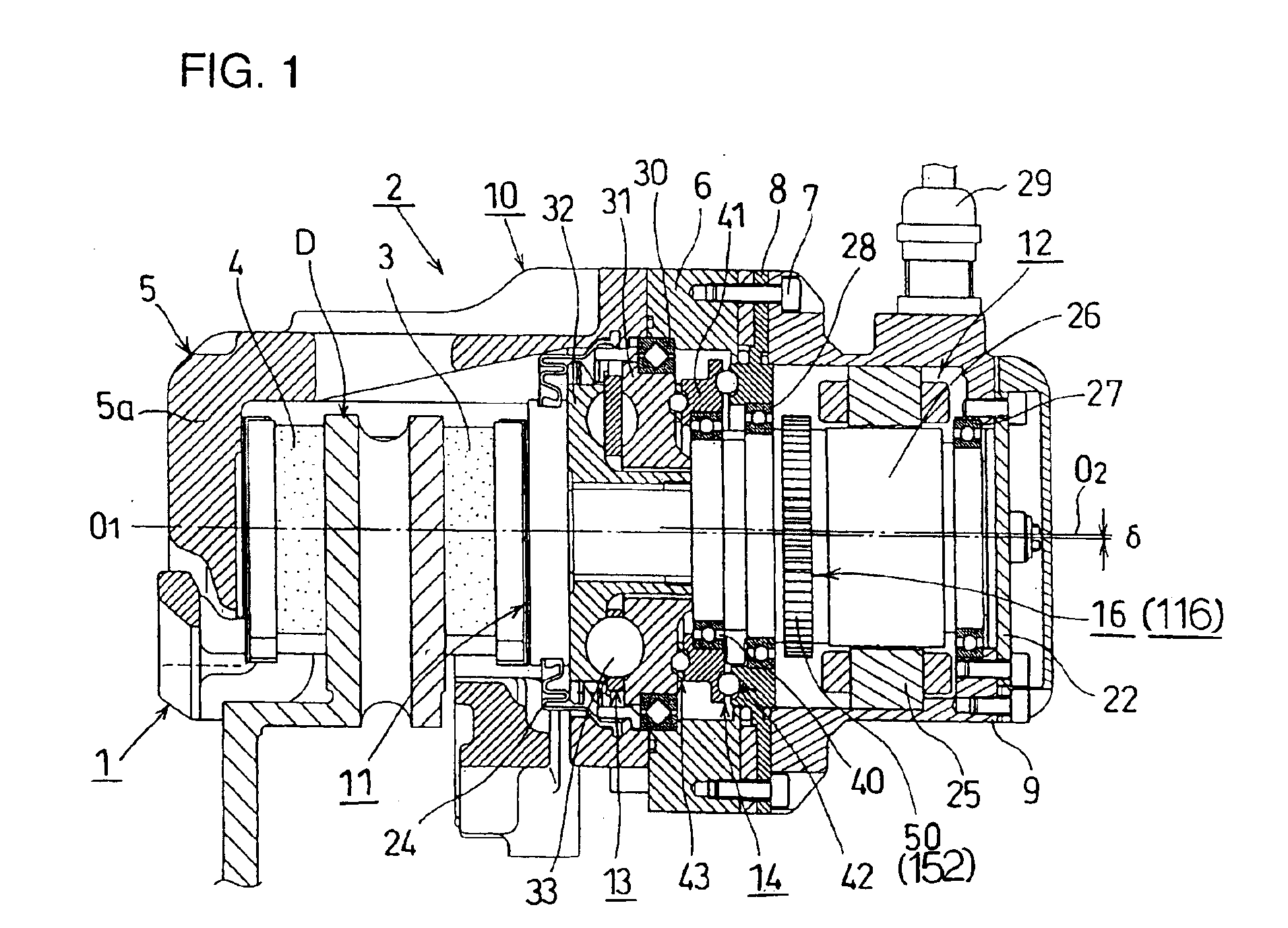
[0037]An explanation will be given of operation of the electric braking apparatus also in reference to FIG. 4 and FIG. 5.
(In Operating Electric Brake)
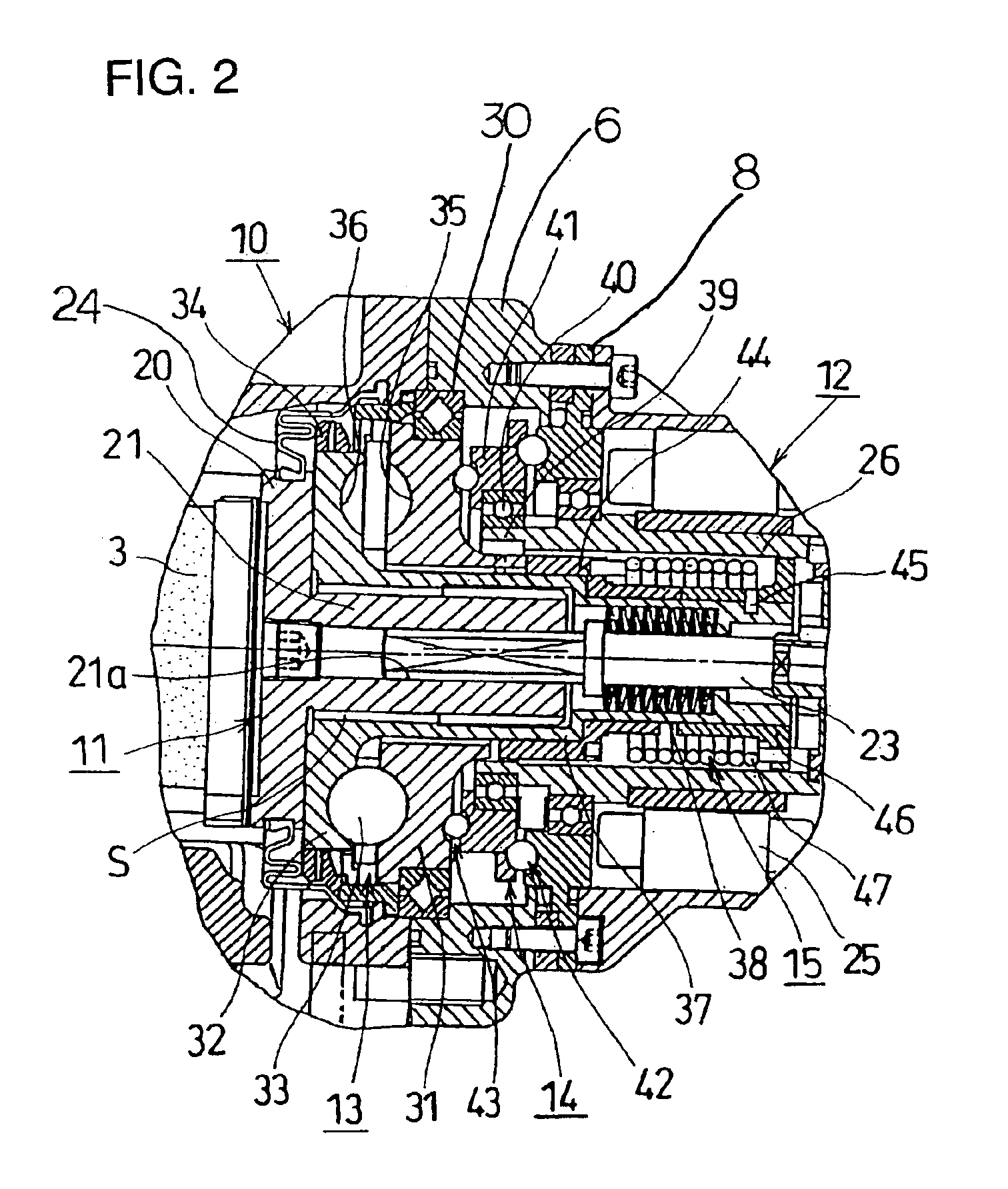
[0038]When the apparatus is operated as a normal electric brake, the rotor 26 of the motor 12 rotates in the clockwise direction as viewed from the right in FIGS. 1 and 2 upon input of a braking signal from the driver. Then, the eccentric plate 41, since attached via the bearing 40 to the eccentric shaft 39 formed integrally with the rotor 26, revolves, not rotate, by the Oldham mechanism 42. By the revolusion of the eccentric plate 41, the cycloid ball speed reducing mechanism 43 is operated and the first disk 31 of the ball ramp mechanism 13 is rotated in the reverse direction (counterclockwise) at a speed in a constant ratio N to that of the rotor 26 as described above. Meanwhile, the rotation of the second disk 32 of the ball ramp mechanism 13 is restricted due to the resistance force by the wave washer 34. Accordingly, the second...
second embodiment
[0045]An explanation will be given of operation of the electric braking apparatus according to the
(Actuating the Electric Brake)
[0046]In the normal operation of the electric braking apparatus, the rotor 26 of the motor 12 rotates clockwise as seen from the right in FIGS. 1 and 2. When the driver inputs the brake operating signal, as happens in the first embodiment, the piston 11 moves to generate braking force proportional to the torque of the motor 12. Further, when the electric brake is operated, simultaneously with supply of electricity to the motor 12, electricity is also supplied to the solenoid 62 of the brake locking mechanism 16. As a result, the plunger 61 of the solenoid 62 extends as shown in FIG. 7. The arm lever 52 is thus held inclined away from the claw wheel 50. When the arm lever 52 is inclined, the engaging claw 54 is held in a position where it is slightly away from the tooth portion 57 of the claw wheel 50, so that the rotor 26 becomes free in rotation in the clo...
third embodiment
[0052]An explanation will be given of operation of the electric braking apparatus according to the
(Activating the Electric Brake)
[0053]When the apparatus performs the normal braking operation, with a brake operating signal from the driver, the rotor 26 of the motor 12 rotates clockwise as viewed from the right in FIGS. 1 and 2. The piston 11 then moves, as it does in the first and the second embodiments, to generate braking force proportional to the torque of the motor 12. Further, when the electric brake is in operation, supply of electricity to the solenoid 62 of the brake locking mechanism 16 is cut off. Thus, as shown in FIG. 9, the engaging claw 54′ is placed slightly away from the tooth portion 57 of the claw wheel 50 by the urging force of the tensile spring 71. As a result, the rotor 26 becomes free in rotation in the clockwise direction R, whereby the function as the electric brake is assured. Also, since the rotor 26 rotates while the engaging claw 54′ is away from the cla...
PUM
 Abstract
Description
Claims
Application Information
 - R&D
- Intellectual Property
- Life Sciences
- Materials
- Tech Scout
- Unparalleled Data Quality
- Higher Quality Content
- 60% Fewer Hallucinations
Browse by: Latest US Patents, China's latest patents, Technical Efficacy Thesaurus, Application Domain, Technology Topic, Popular Technical Reports.
© 2025 PatSnap. All rights reserved.Legal|Privacy policy|Modern Slavery Act Transparency Statement|Sitemap|About US| Contact US: help@patsnap.com


