
Apparatus for providing aerosol for medical treatment and methods

Inactive Publication Date: 2005-07-12
NOVARTIS FARMA
View PDF12 Cites 40 Cited by
  • Summary
  • Abstract
  • Description
  • Claims
  • Application Information

AI Technical Summary

Benefits of technology

[0013]In certain embodiments, the method further comprises applying at least one layer of bonding material between the mold material and least one of the vibratory element and the actuator. Applying at least one layer can include applying a layer of a first bonding material and applying a layer of a second bonding material. The first bonding material and the second bonding material can be the same bonding materials. One or more layers can be applied at room t

Problems solved by technology

In use, aerosol generators can be subjected to a variety of environmental conditions, many of which can threaten to degrade the performance of the generator; for instance, during operation, the piezo and / or the electrodes may be in danger of exposure to the fluid being aerosolized.
Those skilled in the art will recognize that, in many cases, prolonged exposure to such fluids can result in corrosion of the piezo and / or the electrodes, and even relatively brief exposure can vitiate the electrical communication between the piezo and the circuitry by which it is driven (for example, by short-circuiting the electrodes and / or otherwise interfering with the electrical communication between the electrodes and the piezo).
Likewise, various cleaning procedures can prove harmful to the operation of the aerosol generator if care is not taken.
In addition, generators may be exposed to relatively high levels of heat, pressure, and / or humidity during sanitization processes, such as autoclaving and the like.
Without protection, therefore, the relatively sensitive components of aerosol generators (including, for example, their piezos and / or electrodes) may be damaged during sanitization and / or the operational lives of such components may be limited significantly by repeated sanitization procedures.

Method used


Image

  • Apparatus for providing aerosol for medical treatment and methods
  • Apparatus for providing aerosol for medical treatment and methods
  • Apparatus for providing aerosol for medical treatment and methods

Examples


Embodiment Construction

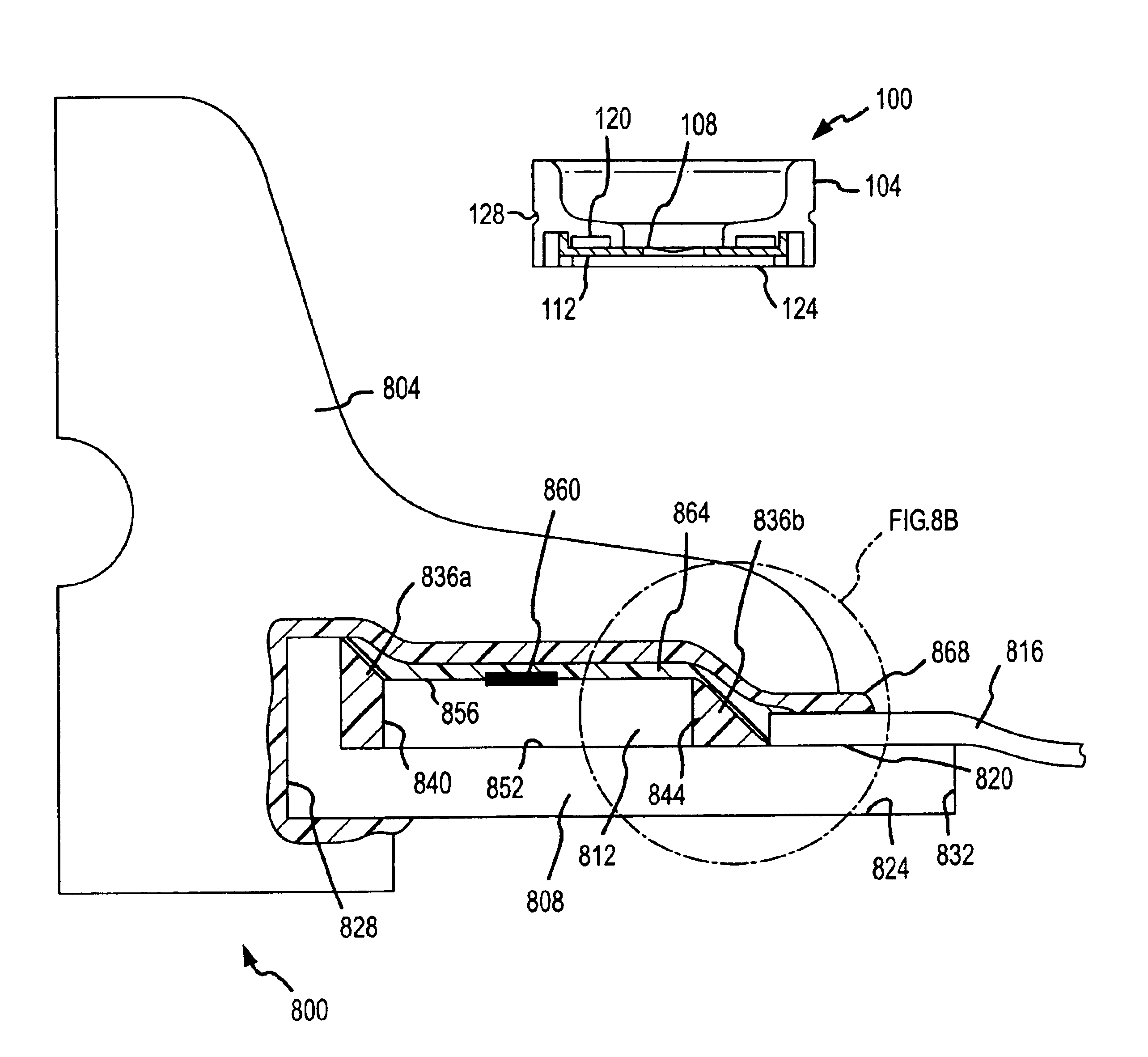
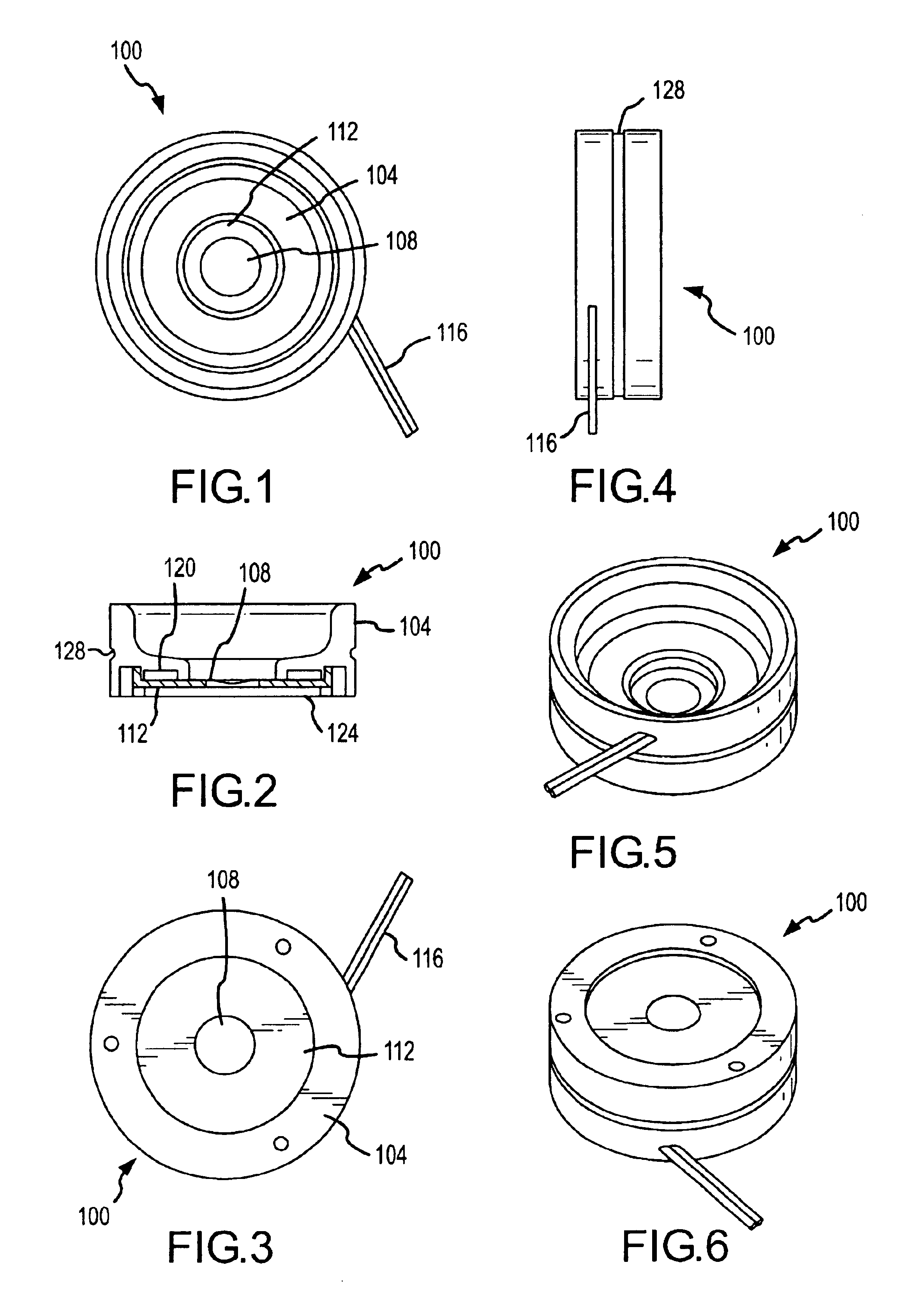
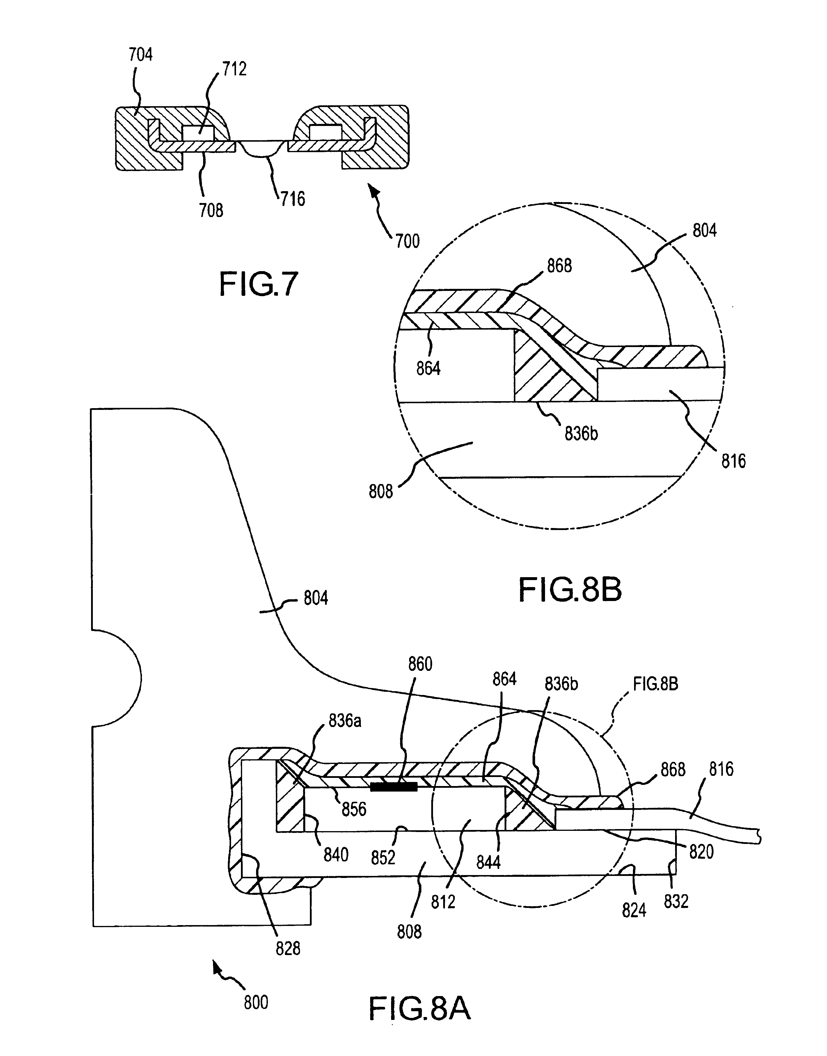
[0034]Embodiments of the present invention include apparatus and methods for aerosolizing liquid. In accordance with one embodiment, an aerosol generator assembly is provided, comprising an aerosol generator and a sealing element overmolded onto the aerosol generator. Those skilled in the art will appreciate that, in accordance with certain embodiments of the invention, an aerosol generator comprises a piezoelectric and / or piezomagnetic vibratory element (a “piezo”) for vibrating an aerosolization element to aerosolize a fluid. In many cases, the piezoelectric member is driven by application of an electric and / or magnetic field, which often is supplied through an electric circuitry coupled to the piezo by one or more electrodes. The connection between the circuitry and the electrodes can be of any type that is operative to supply electric current to the piezo, including, for instance, conductive metal wires (optionally, with non-conductive insulation), conductive polymeric materials...


PUM


Abstract

Embodiments of the present invention include apparatus and methods for aerosolizing liquid. One embodiment of the invention provides an apparatus for generating an aerosol. The apparatus includes an actuator having a first face and a second face and defining an opening therethrough, as well as a vibratory element in mechanical communication with the actuator, and a sealing member configured to isolate the vibratory element from a surrounding environment. In accordance with certain embodiments, the apparatus further comprises an aerosolization element mounted on the actuator and disposed substantially over the opening, wherein the aerosolization element defines at least one aperture therethrough. Hence, the vibratory element may be operated to vibrate to cause movement of the aerosolization element in such a manner that a liquid at the first face of the aerosolization element can be dispensed as an aerosol through the at least one aperture. Some embodiments feature an electrode coupled to the vibratory element.

Description

CROSS-REFERENCES TO RELATED APPLICATIONS[0001]This application is a nonprovisional of provisional U.S. Patent App. Ser. No. 60 / 382,256, entitled “APPARATUS AND METHODS OF PROVIDING AEROSOL FOR MEDICAL TREATMENT,” filed May 20, 2002 by Power et al., the entire disclosure of which is incorporated herein by reference for all purposes.BACKGROUND OF THE INVENTION[0002]This invention relates generally to the field of pulmonary drug delivery, and in particular to the aerosolizing of liquid medicament into fine liquid droplets for inhalation.[0003]In the fields of drug delivery and pulmonary therapy, the aerosolization of drugs and other medicaments for pulmonary delivery can provide significant therapeutic benefits. To realize those benefits, there have arisen a variety of atomizers and nebulizers, which can vary significantly in methods of operation. For instance, some aerosol generators operate by vibrating at a relatively high frequency an aperture plate in contact with the material to ...

Claims


Application Information

Patent Timeline
IPC IPC(8): B05B17/04B05B1/02B05B1/08A61MA61M1/00A61M11/00A61M15/00B05B1/00B05B1/14B05B3/04
CPCA61M11/005A61M15/0085B05B17/0646
Inventor POWER, JOHNREGAN, DESSMITH, NIALL
Owner NOVARTIS FARMA
Learn More