
Ventilation device for a high pressure turbine rotor of a turbomachine

a technology of turbine rotor and ventilation device, which is applied in the direction of machines/engines, stators, liquid fuel engines, etc., can solve the problems of high production cost, high production cost, and extremely complex design of the upstream labyrinth, and achieves reduced supply pressure to blades, improved control of blade tip clearance, and compact structure

Active Publication Date: 2005-07-12
SN DETUDE & DE CONSTR DE MOTEURS DAVIATION S N E C M A
View PDF12 Cites 16 Cited by
  • Summary
  • Abstract
  • Description
  • Claims
  • Application Information

AI Technical Summary

Benefits of technology

The invention proposes a ventilation device for a high pressure turbine rotor in a turbomachine. The device includes a cooling circuit with injectors located on the upstream side of the upstream turbine disk, which is supplied by a cooling airflow from the back of the combustion chamber. The cooling airflow passes through orifices in the upstream disk and is fixed onto the downstream disk, circulating between the two disks. The device also includes a single labyrinth positioned between the two turbine disks, which guides the cooling airflow towards the blades. The cooling airflow is sufficient to lower the temperature of the blades, increasing their lifespan. The reduced number of parts and the position of the labyrinth also reduces the mass, size, and production cost of the rotor. The invention also enables fast and easy disassembly of the stator, reducing the clearance at the tip of the blades.

Problems solved by technology

Nevertheless, this conventional solution according to prior art is constraining in the sense that the design of the upstream labyrinth is extremely complex, heavy and its production cost is very high, particularly due to the need to use special materials capable of resisting high intensity thermal loads.
Moreover, the life of the upstream labyrinth is relatively limited even when good quality materials are used.

Method used


Image

  • Ventilation device for a high pressure turbine rotor of a turbomachine
  • Ventilation device for a high pressure turbine rotor of a turbomachine
  • Ventilation device for a high pressure turbine rotor of a turbomachine

Examples


Embodiment Construction

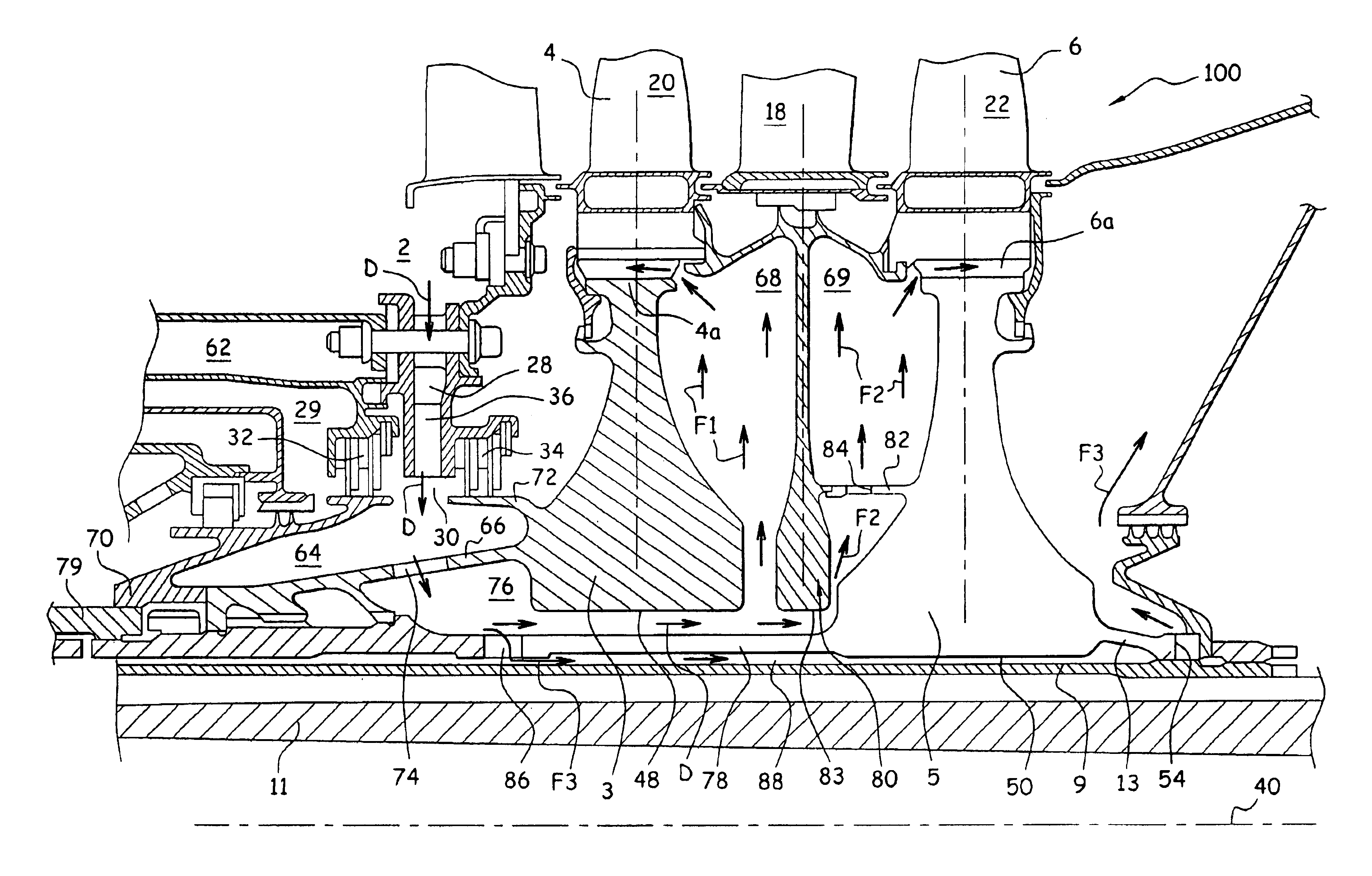
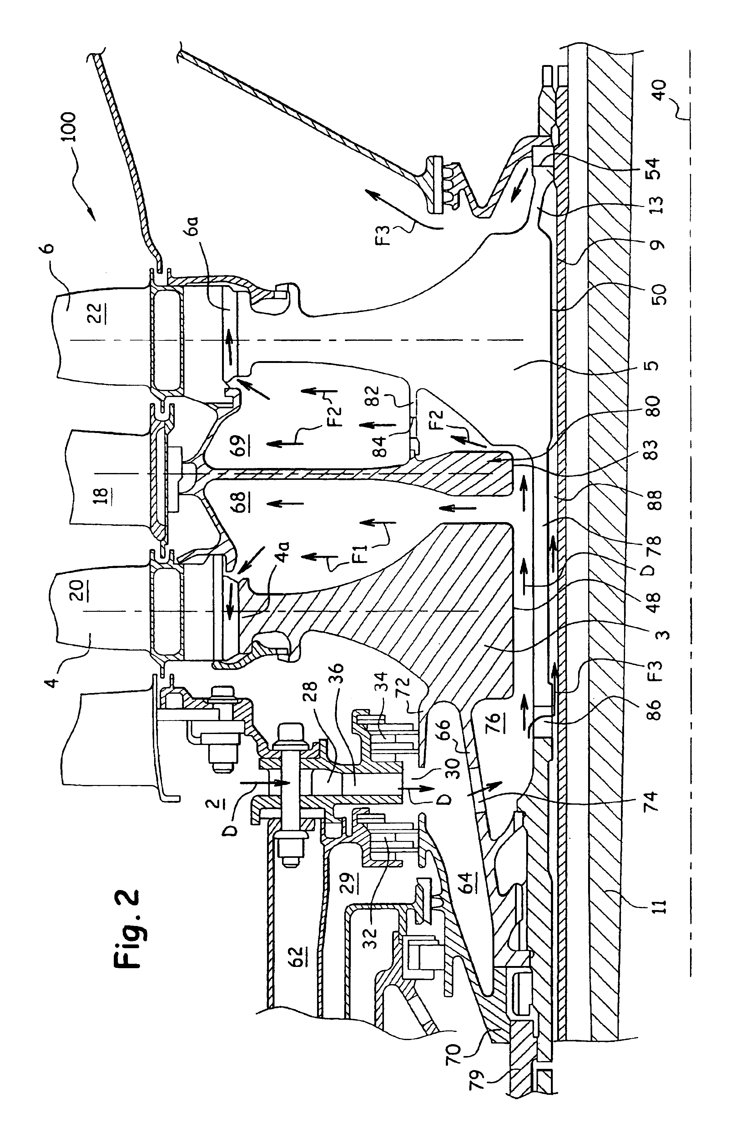
[0028]FIG. 2 shows a high pressure turbine 100 of a turbojet, comprising a ventilation device for the turbine rotor according to a preferred embodiment of this invention. Note in FIG. 2, that elements with the same numeric references as elements shown in FIG. 1 correspond to identical or similar elements.

[0029]Thus, FIG. 2 shows a turbine 100 that is different from the turbine 1 according to prior art firstly due to the fact that a cooling airflow D taken from the back of the combustion chamber 2 and that can pass through injectors 36, will supply blades 4 and 6 of the upstream disk 3 and downstream disk 5 simultaneously.

[0030]In fact, the cooling airflow from the combustion chamber 2 passes through the duct 28 to reach the injectors 36, this assembly composed of the duct 28 and the injectors 36 being located in a chamber 62 separating the upstream disk 3 from, the back of the combustion chamber 2.

[0031]The cooling airflow D originating from the injectors 36 then penetrates into a c...


PUM


Abstract

A ventilation device for a high pressure turbine rotor in a turbomachine, the turbine comprising upstream and downstream turbine disks fitted with blades, the device comprising a cooling circuit being supplied by a cooling airflow D taken from the back of the combustion chamber. The circuit is such that the airflow passes through orifices formed in an upstream flange of the upstream disk, such that this airflow circulates in the axial direction towards the downstream side between an inner reaming of the upstream disk and a downstream flange of the downstream disk, the device also comprising a labyrinth inserted between the two disks, such that the airflow is divided into a first flow F1 and a second flow circulating on each side of labyrinth towards the blades.

Description

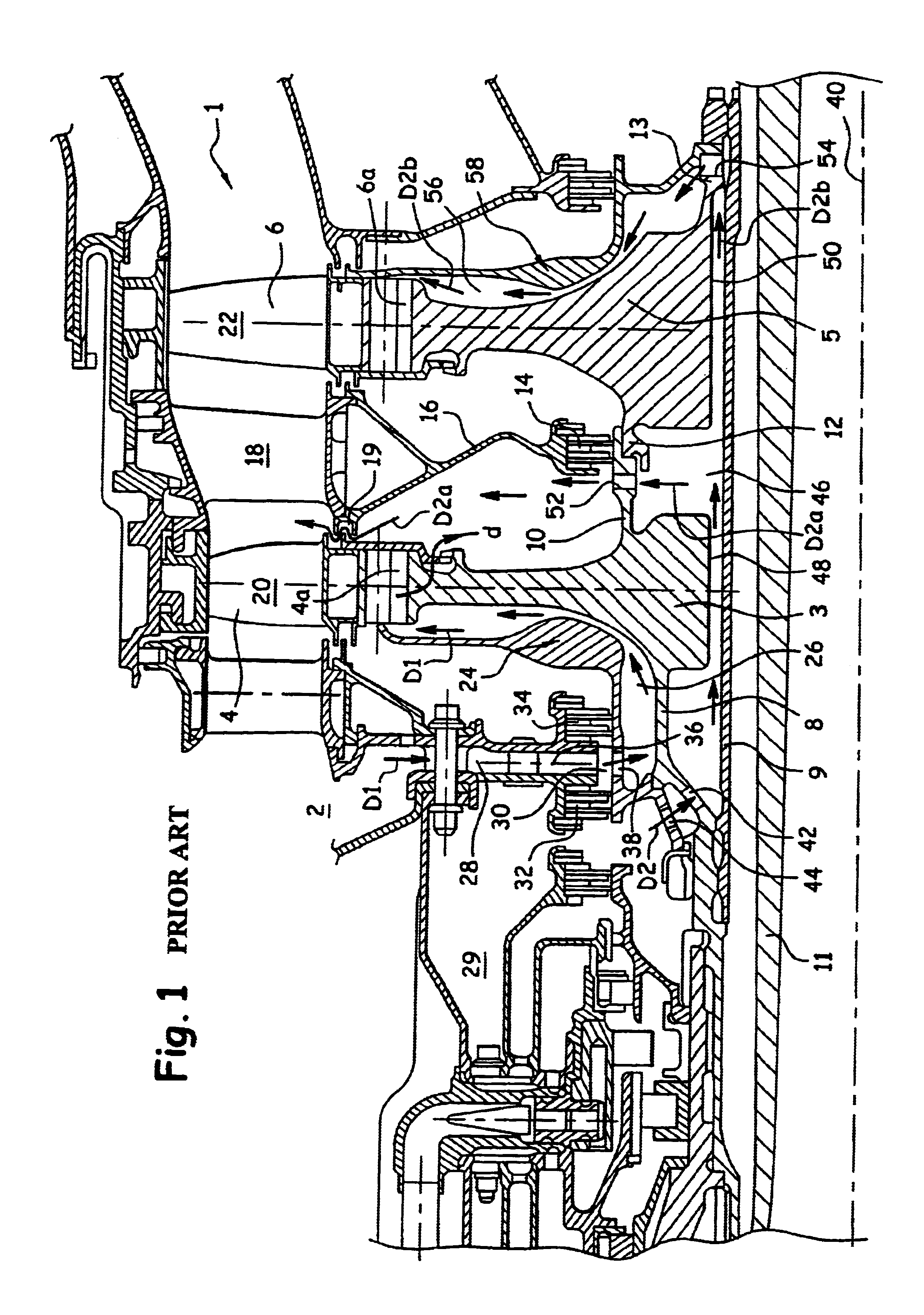
TECHNICAL FIELD[0001]This invention relates in general to the ventilation of a high pressure turbine rotor in a turbomachine.[0002]More precisely, the invention relates to a ventilation device for a high pressure turbine rotor comprising an upstream turbine disk and a downstream turbine disk.STATE OF PRIOR ART[0003]FIG. 1 shows a conventional high pressure turbine rotor 1 according to prior art, arranged on the downstream side of a combustion chamber 2, and comprising an upstream turbine disk 3 equipped with blades 4, and a downstream turbine disk 5 equipped with blades 6.[0004]The upstream disk 3 is provided firstly with an upstream flange 8 that attaches it to a spacer 9 arranged around a rotor shaft 11 of a low pressure turbine, and secondly a downstream flange 10 rigidly assembled to an upstream flange 12 of the downstream disk 5. Note that there is an inter-disk seal 14, supported by a hollow structure 16 fixed to a fixed distributor stage 18 or stator, at the assembly between ...

Claims


Application Information

Patent Timeline
Patent Type & Authority Patents(United States)
IPC IPC(8): F01D5/02F01D5/08F01D1/00F02C7/18
CPCF01D5/082
Inventor JUDET, MAURICEROSSI, PATRICKTAILLANT, JEAN-CLAUDE
Owner SN DETUDE & DE CONSTR DE MOTEURS DAVIATION S N E C M A
Learn More