Weight sensors having centralized loose tolerance universal force and Mx/My moments overload stops

a weight sensor and universal force technology, applied in the field of load cells, can solve the problems of sensor physical separation, false or distorted sensor output, mechanical or electrical failure of the sensor, etc., and achieve the effect of reducing the thickness increasing the yield strength of the sensor substrate, and increasing the force applied

Inactive Publication Date: 2005-07-12
ROBERT BOSCH CORP
View PDF9 Cites 69 Cited by
  • Summary
  • Abstract
  • Description
  • Claims
  • Application Information

AI Technical Summary

Benefits of technology

[0018]In addition the inventive directly mounted concave springs design is applicable to non-limit-stop design load cells to provide greater travel, both in the Z direction and to compensate for Mx and My moments.
[0041]Thus, the inventive loose tolerance multi-axial moment and Z axis overload stop subassembly may be applied to and adapted for any type of load cell design, including non-load-stop designs and load stop designs using sensor substrates of standard rectangular, notched, necked / dog bone, cantilevered, or the like design. The capacity of the load cell, in terms of applied force (e.g., weight in pounds) can be increased by stiffening the limit stop component, and / or by selecting (increasing) the yield strength of the sensor substrate. The preferred range of measurement for the sensor substrate is in the range of about ±200 lbs. The sensor substrate type and thickness is preferred to be sufficient to not yield when a 600-1000 lb force is applied. Sensor substrate thickness typically ranges from about 1.8 mm to about 4 mm, preferably about 2 to 3 mm. For example, for a 430-type stainless steel substrate, the minimum thickness is on the order of 2 mm, and the preferred is in the range of about 2.3 to about 3 mm. Sensor substrate thickness can be reduced by reducing the measurement range, which requires subjecting the sensor substrate to a lower load. In designs where maximum measurement load is reduced, the thickness of the sensor substrate can be reduced. In addition, by stiffening the limit stop bracket, its deflection during overload is reduced. Thus, it reduces the load on the sensor substrate after the limit stop is engaged.

Problems solved by technology

It is essential to keep the deflection of the sensor substrate in the elastic region of the sensor substrate material's yield strength over the typical range of automotive use, including environment temperature variation, which is on the order of −40 to +90° C. Deformation beyond the elastic limit of the substrate under load can result in false or distorted sensor output and ultimately to mechanical or electrical failure of the sensors, including physical separation of the sensors from the substrate.
Of course, erroneous or false readings or failure will lead to improper inputs to the airbag controller, possibly resulting in deployment when the seat is empty, or non-deployment when it is occupied, both unwanted results.
This is expensive, adds weight to the seat and also occupies precious packaging space in the seat.
If the moments are not filtered out, the sensor substrate can quickly fail under a twist about the longitudinal or transverse axis of the sensor—without an overload stop for moments.
Even small yields can lead to false, erroneous readings or failure.
The thickness dimension of the sensor substrate, being relatively thin, limits the load capacity of the sensor substrate.
That is, if the sensor substrate is too thick, it will not measurably deflect under load, the deflection is difficult to measure, or the measurements become inconsistent and subject to thermal condition interference (thermal noise).
To obtain greater range of gauge readings, the sensor substrate can be made thinner, but the serious disadvantage is that the range of deflection before yield is reduced, and the load capacity of the load cell is reduced.
In addition, thinner substrates are more prone to distortions and failure under Mx and My torsional forces.
Since the load cells are expensive to produce, and generally are currently assembled and mounted to the seat during seat construction, adding more load cells is not a realistic alternative.
This precision is difficult to achieve, particularly over large production runs, and even more difficult to maintain over time within the environmental conditions of automotive use, particularly vibration, large thermal range, and passenger misuse.
Further, failed load cells are difficult and expensive to repair, as they generally require substantial, if not entire, disassembly of the seat.

Method used


Image

  • Weight sensors having centralized loose tolerance universal force and Mx/My moments overload stops
  • Weight sensors having centralized loose tolerance universal force and Mx/My moments overload stops
  • Weight sensors having centralized loose tolerance universal force and Mx/My moments overload stops

Examples


first embodiment

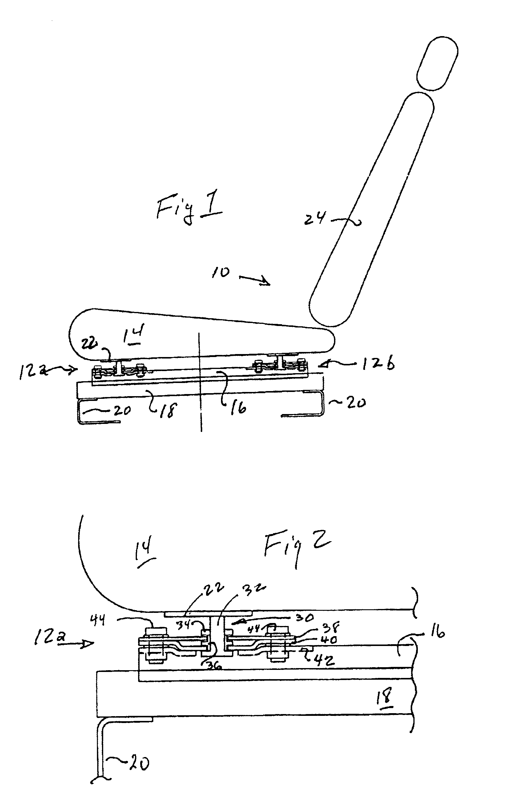
[0062]FIG. 1 is a side elevation view, in schematic and partly in section, showing a full vehicle seat 10 with a load cell assembly 12 of the invention mounted between the seat 14 and the upper rail 16. The seat unit includes a lower rail 18, seat riser bracket 20, seat pan mounting plate 22 and seat back 24. The seat elements are conventional.

[0063]Four load cells are used, located generally at the corners of the seat pan, the two shown, 12a and 12b, being repeated on the other side of the seat.

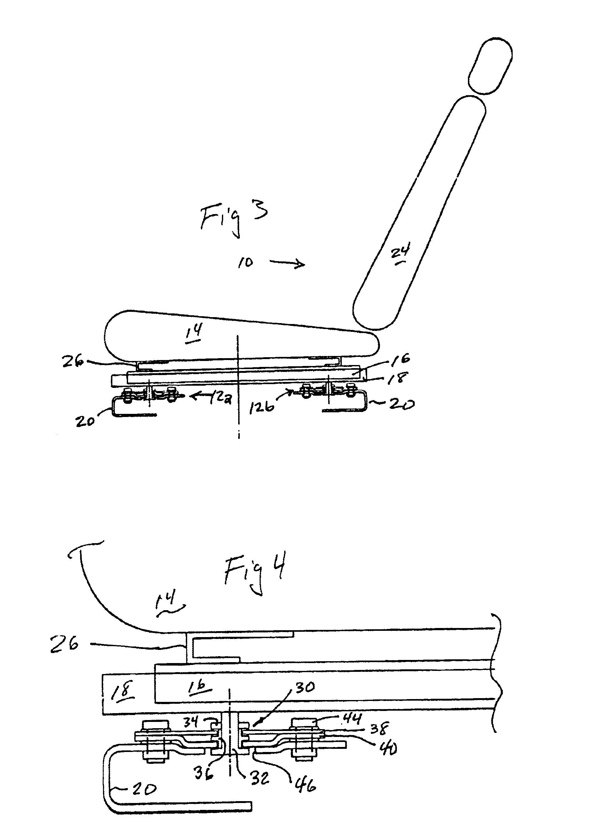
[0064]FIG. 2 is a side elevation view, in partial section, showing the load cell 12a of FIG. 1 employing the inventive loose tolerance overload limit stop assembly 30, which comprises load stud 32, hex nut 34 and load limit stop guide 36. The load cell includes sensor substrate plate 38, limit stop bracket 40, and rail mounting bracket 42, and support bolts 44.

[0065]FIG. 3 is a side elevation view, in schematic and partly in section, showing a full vehicle seat 10 with the FIG. 1 load cell 1...

second embodiment

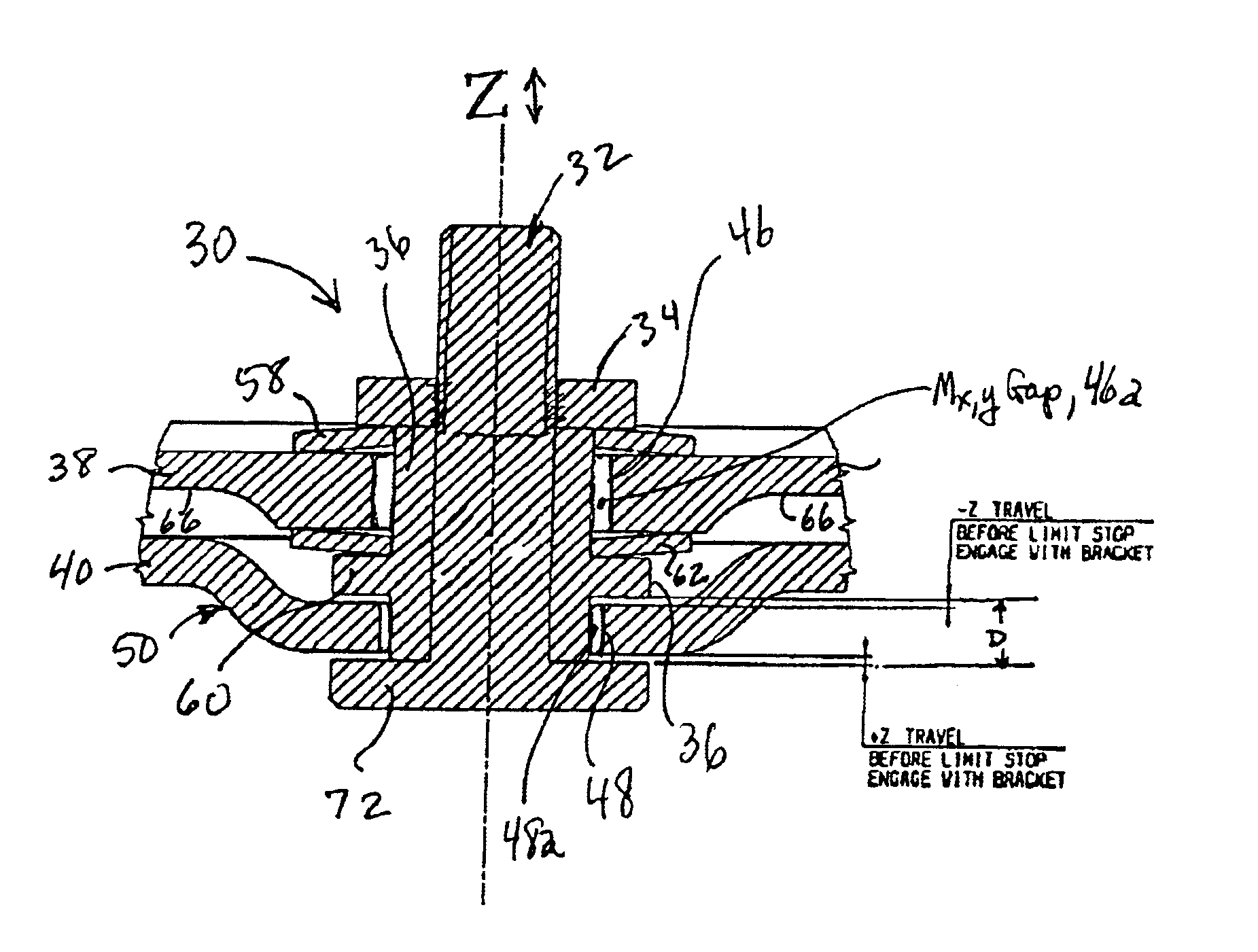
[0066]FIG. 5 is a longitudinal section view through a load cell 12 of the invention showing the detail of one embodiment of the inventive loose tolerance overload limit stop assembly 30, in this case employing a multi-part load stud 32a, 32b received in the limit stop guide 36. As above, the sensor substrate plate center hole 46 receives the stop guide 36. In turn the sensor substrate is supported by the limit stop bracket 40, which in this embodiment includes a center aperture 48 for receiving the lower end of the stop guide 36 in a central recess 50. Note that the substrate gap 46a, that is the gap formed between the wall of the hole in the substrate 46 and the outer surface of the guide 36, is larger than the gap in the limit stop bracket 48a, that is, the gap formed between the hole in the bracket 48 and the surface of the guide 36. (This is also illustrated in the enlarged FIG. 8, where the gap 46a is also referred to as the Mx / My gap.) The angular compensation and magnificatio...

third embodiment

[0076]FIG. 12 is a side elevation view, partly in section of a load cell 12 of the invention showing use of the inventive loose tolerance limit stop 30 as mounted to a support bracket, e.g., an upper slide or a seat riser bracket 16. The load stud is bolted to a seat pan bracket 22 / 26 / 74. In this embodiment, an upper retaining ring 90, such as a snap-on C-ring is the keeper for the upper Bellville spring, and a similar lower retaining ring 92 functions as the limit stop flange for the load stud 32. Note the thinned sections 66 longitudinally of the stud, and the enlarged support lugs 94 in which the support bolts 78 are received. The distribution of the strain gauges 88 is better shown in FIG. 13, below.

[0077]FIG. 13 is a plan view of the load cell of FIG. 12 showing the location of the strain gauges 88 symmetrical about both axes 68, 70 of the sensor substrate. In this embodiment eight strain gauges are used, and they may be wired in a wide variety of configurations: opposed Wheats...


PUM


Abstract

Automotive load cells having centralized, multi-axis, loose tolerance overload / limit stops provide improved strain gauge response. The modular, integrated stop assemblies magnify sensor substrate deflection by use of opposed concave (Belleville) springs are used in direct contact with the substrate to accommodate ±Z axis deflection and Mx / My moment angular rotation. A flanged guide member on the load stud permits a wide range of geometries. The substrate is thickened around the load stud hole and the outboard support bolt holes. Hollow rivets assist in design modularity. Strain gauges are placed at the yield zones symmetrically with respect to the X axis. The substrate hole Mx / My gap is larger than the stop bracket hole to insure a positive stop for Mx / My moments prior to yield. The inventive multi-axis stop assembly is used in any type load cell, including rectangular, thinned, notched, necked / dogbone, or cantilever substrates with any strain gauge layout configuration.

Description

CROSS-REFERENCE TO RELATED CASE[0001]This is the Regular U.S. Application of U.S. Provisional Application Ser. No. 60 / 337,774, filed by us on 7 Dec. 2001, entitled Loose Tolerance Overload Stop Assembly for Load Cells, the priority of which is claimed under 35 US Code 119, and related treaties.FIELD OF THE INVENTION[0002]This invention relates to automotive occupancy weight sensor systems, and more particularly to improved load cells for automotive seats. The inventive load cells include compact, multidimensional, centralized, loose tolerance universal force and Mx / My moment stops for weight overloads that permit lower cost manufacturing and higher sensitivity of the load cell in the measurement range while preventing damage in overload situations.BACKGROUND OF THE ART[0003]Motor vehicles are equipped with safety belts and airbags for passenger safety. A wide variety of occupant sensors provide input to the Airbag Control Module (ACM) relating to the presence or absence of occupants...

Claims


Application Information

Patent Timeline
Patent Type & Authority Patents(United States)
IPC IPC(8): B60R21/01G01G19/414G01G19/40B60R21/015
CPCG01G19/4142B60R21/01516B60R21/0152G01G23/002
Inventor THAKUR, RAJEEVGOLSHTEYN, ALEXANDERWATTS, RUSSLEE, DARRENDAS, RAJESH
Owner ROBERT BOSCH CORP
Why Eureka
Try Eureka