Frequency tunable optical oscillator with fiber grating mirrors

a technology of optical oscillators and fiber grating mirrors, applied in the direction of laser details, active medium materials, active medium shape and construction, etc., can solve the problems of complex structure, inapplicability to the frequency band being studied, and inability to use optical oscillators using optical modulators

Inactive Publication Date: 2005-07-12
ELECTRONICS & TELECOMM RES INST
View PDF1 Cites 6 Cited by
  • Summary
  • Abstract
  • Description
  • Claims
  • Application Information

AI Technical Summary

Problems solved by technology

The optical oscillators using optical modulators have a frequency band limited to 30 GHz at most, and accordingly they are not suitable for a frequency band that is being currently studied.
Also, the optical oscillators using optical modulators are not practical because it is difficult to manufacture an optical source.
The optical oscillators proposed by the present applicants are improved versions of conventional optical oscillators but have complicated structures because two individual fiber laser resonators must be combined using a fiber coupler.

Method used


Image

  • Frequency tunable optical oscillator with fiber grating mirrors
  • Frequency tunable optical oscillator with fiber grating mirrors
  • Frequency tunable optical oscillator with fiber grating mirrors

Examples


Embodiment Construction

[0021]Hereinafter, embodiments of the present invention will be described in detail with reference to the attached drawings. The present invention may, however, be embodied in many different forms and should not be construed as being limited to the embodiments set forth herein; rather, these embodiments are provided so that the present disclosure will be thorough and complete, and will fully convey the concept of the invention to those skilled in the art.

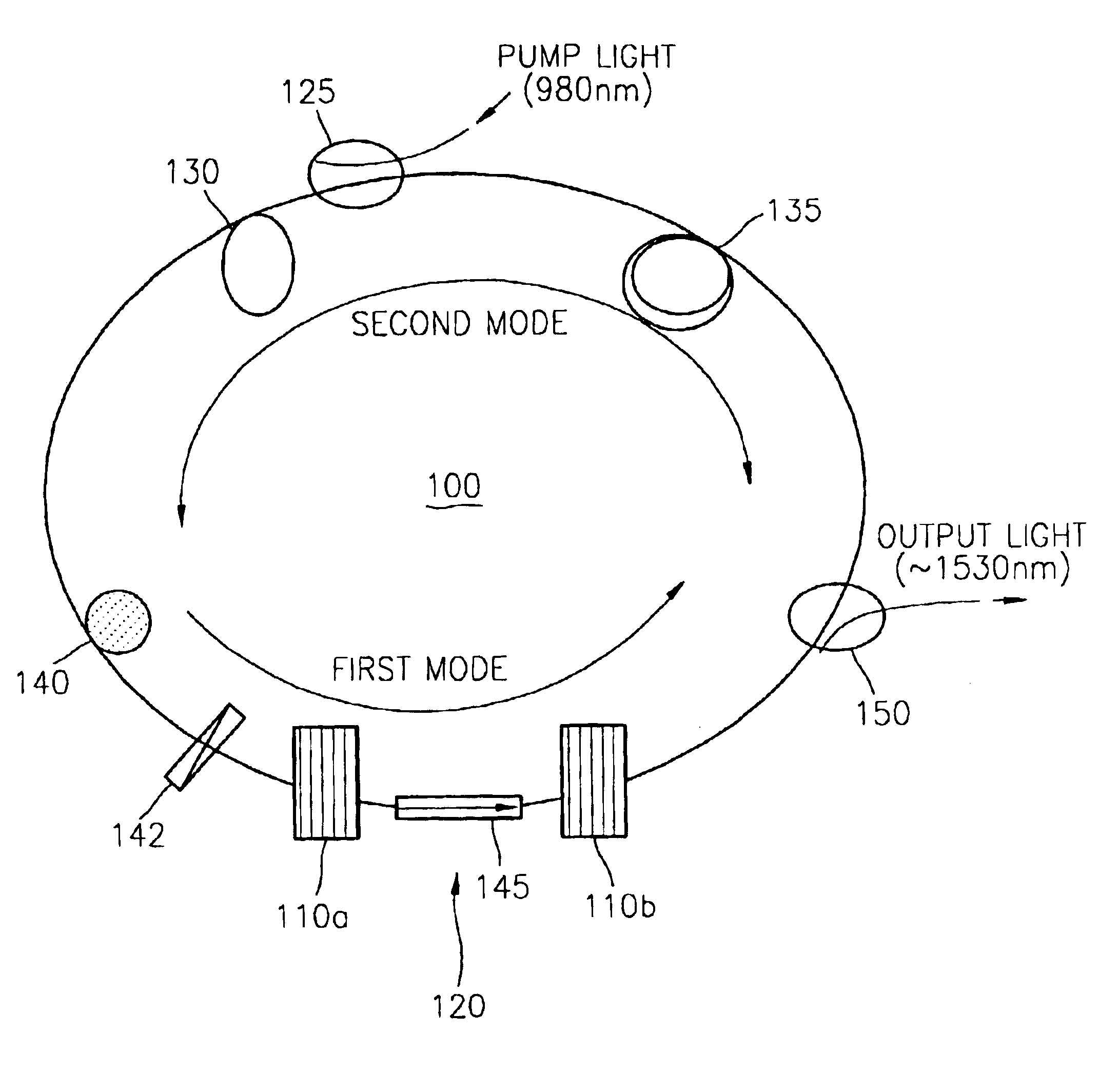
[0022]Referring to FIG. 1, an optical oscillator using fiber grating mirrors, according to the present invention, is basically constituted of a single fiber-ring laser resonator 100. In the optical oscillator, a pair of fiber grating mirrors 110a and 110b, in which the wavelength of light that can be reflected varies, are installed within the fiber-ring laser resonator 100 such that a linear laser resonator 120 which reciprocates between the two fiber grating mirrors 110a and 110b is added to the inside of the optical oscillator. Du...


PUM


Abstract

There is provided a millimeter wave band frequency optical oscillator predicted to be used as a millimeter wave oscillating frequency signal source in a base station of a millimeter wave wireless transmission system. The optical oscillator has a double resonator structure in which a pair of wavelength tunable fiber grating mirrors are inserted into a unilateral fiber-ring laser resonator in order to internally and additionally form a linear laser resonator. The double resonator structure composed of the two stable laser resonators can oscillate laser of two modes. Due to a beat phenomenon occurring between the two modes, received laser is modulated to an ultra-speed frequency of 60 GHz or greater. A variation in the gain within a resonator is induced by a polarization controller using the dependency of laser modes upon polarization. A modulation frequency is consecutively changed from 60 GHz to 80 GHz by controlling the wavelength of light reflected by the fiber grating mirrors.

Description

BACKGROUND OF THE INVENTION[0001]This application claims the priority of Korean Patent Application No. 2002-67053, filed on Oct. 31, 2002, in the Korean Intellectual Property Office, the disclosure of which is incorporated herein in its entirety by reference.[0002]1. Field of the Invention[0003]The present invention relates to a high frequency optical oscillator in the field of wireless telecommunications, and more particularly, to a millimeter wave band frequency optical oscillator.[0004]2. Description of the Related Art[0005]Next-generation ultra-speed wireless Internet services can transmit a large capacity (about 100 Mbps) of information, which is 10 times or greater than the information transmitted by existing wireless Internet service, to wireless subscribers. In order to achieve this, millimeter wave wireless transmission systems that transmit a large capacity of information have been actively developed. In the millimeter wave wireless transmission systems, a millimeter wave ...

Claims


Application Information

Patent Timeline
Patent Type & Authority Patents(United States)
IPC IPC(8): H01S3/06H01S3/067H01S3/081H01S3/1055H01S3/16H01S3/082H01S3/08H01S3/105H01S3/05
CPCH01S3/06791H01S3/06725H01S3/0675H01S3/08022H01S3/082H01S3/1055H01S3/1608H01S3/05
Inventor KIM, HO-YOUNGNAM, EUN-SOOCHO, KYOUNG-IK
Owner ELECTRONICS & TELECOMM RES INST
Why Eureka
Try Eureka