
Inner tub for washing machine

a technology for washing machines and tubs, which is applied to other washing machines, spin-dryers, textiles and papermaking, etc., can solve the problems of inability to rotate at high speed of inner tubs, inability to support inner tubs, and inability to increase spin-drying speed, so as to increase the drying degree of laundries and reliability of washing machines

Inactive Publication Date: 2005-07-19
LG ELECTRONICS INC
View PDF14 Cites 14 Cited by
  • Summary
  • Abstract
  • Description
  • Claims
  • Application Information

AI Technical Summary

Benefits of technology

[0012]Therefore, an object of the present invention is to provide an inner tub for a washing machine which is able to increase dried degree of laundries and reliability of the washing machine by improving a structure of an inner tub hub to reinforce the inner tub.
[0017]Some parts of the radial supporting portion of the inner tub connected to the rotating shaft coupling portion and the ring type supporting portion are shaped as a curved surface in order to prevent stress from concentrating on that parts.

Problems solved by technology

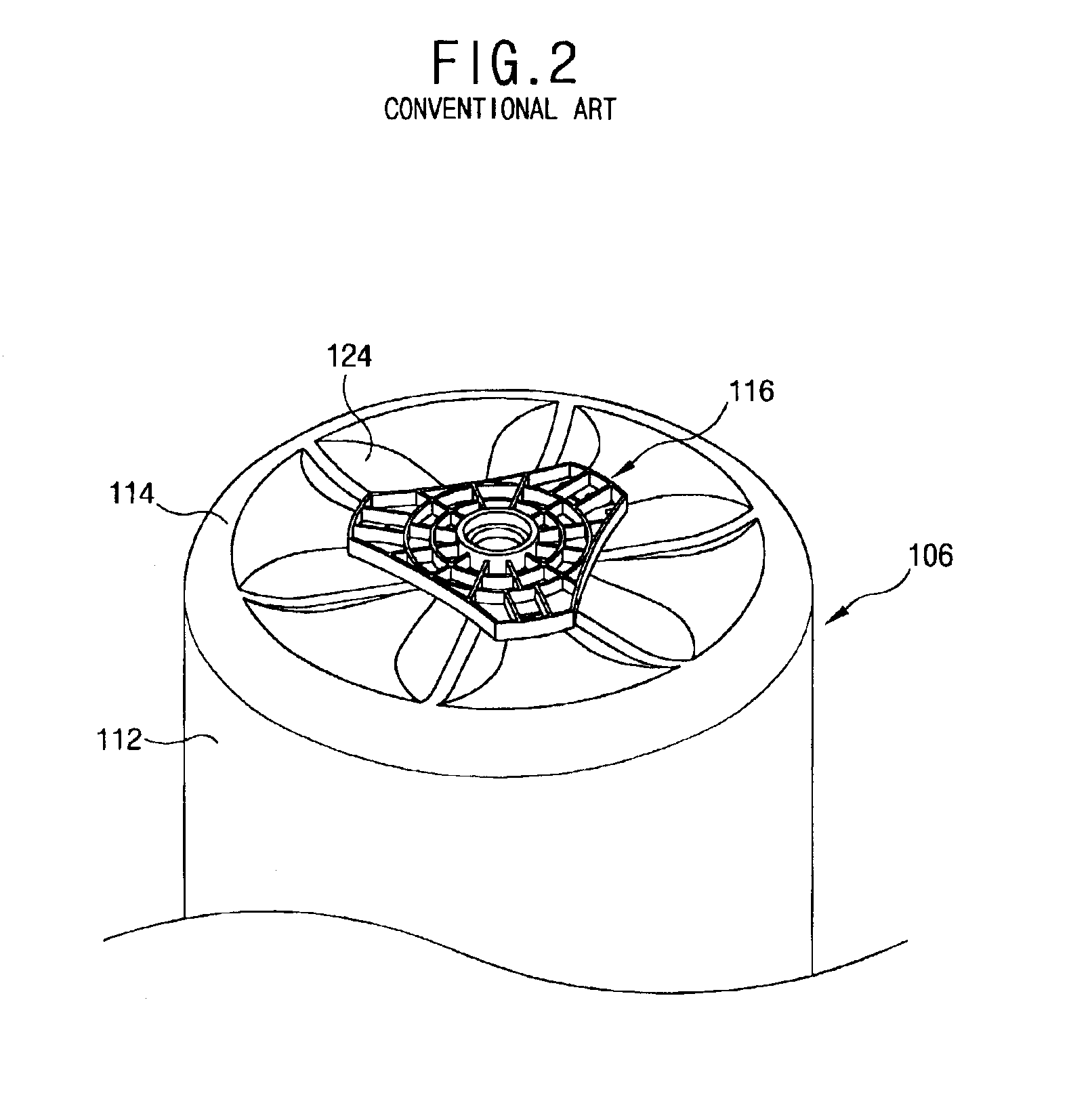
In addition, in the conventional washing machine described above, the inner tub hub is formed as a triangle to couple the rotating shaft, however, the inner tub hub is not able to support the inner tub 106.
Therefore, the rotation at high speed of the inner tub can not be made, and the spin-drying speed can not be increased.
However, in case of increasing the spin-drying speed, the centrifugal force is increased and stress applied to the inner tub is also increased, and thereby, reliability of the washing machine is lowered and vibration and noise are caused.
Especially, it is difficult to increase the spin-drying speed more than a certain degree in a large capacity washing machine.

Method used


Image

  • Inner tub for washing machine
  • Inner tub for washing machine
  • Inner tub for washing machine

Examples


Embodiment Construction

[0037]Reference will now be made in detail to the preferred embodiments of the present invention, examples of which are illustrated in the accompanying drawings.

[0038]There may be a plurality of embodiments for the inner tub in the washing machine according to the present invention, however, the most preferred embodiment will be described as follows.

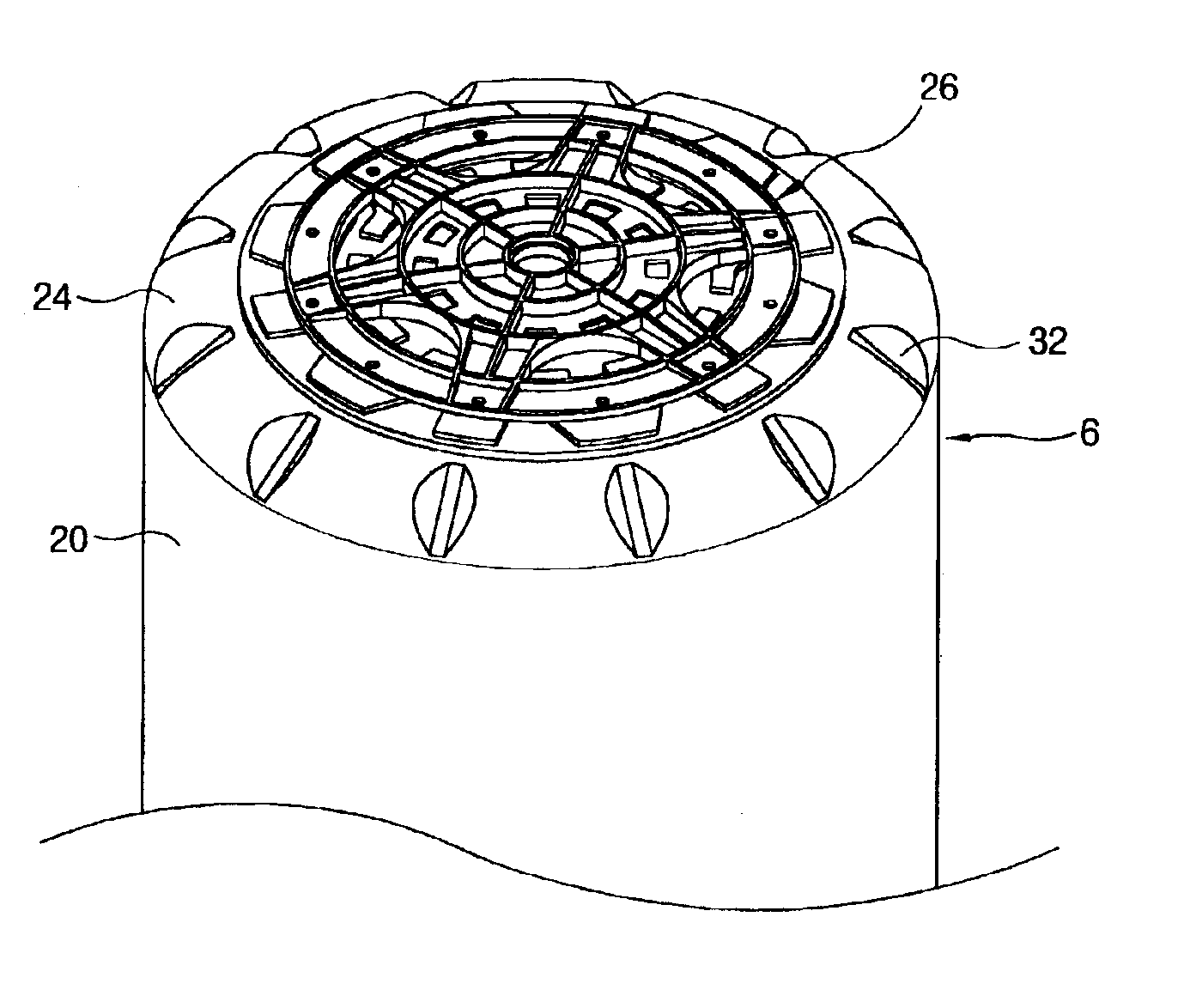
[0039]FIG. 5 is a partial cross-sectional view showing the washing machine according to the present invention, and FIG. 6 is a perspective view showing an inner tub in the washing machine according to the present invention viewing from a rear part.

[0040]As shown in FIG. 5, the washing machine according to an embodiment of the present invention comprises: a case 2 with an opened upper part; an outer tub 4 supported inside the case 2 for storing wash water; an inner tub 6 installed in the outer tub to be rotatable for washing laundries; and a driving motor 10 installed on a lower part of the outer tub 4 and connected to the inner tub using...


PUM


Abstract

An inner tub for a washing machine, which is able to increase a dried degree of laundries and to increase a reliability of the washing machine by improving a structure of an inner tub hub and reinforcing the inner tub to make a spin-drying of high speed possible, comprises an inner tub body; an inner tub base formed on a lower part of the inner tub body; and an inner tub hub coupled on a lower surface of the inner tub base, including a rotating shaft coupling portion to which a rotating shaft for transmitting a rotating force of a driving motor is coupled, a radial supporting portion extended in an outer boundary direction of the rotating shaft coupling portion with a predetermined gap therebetween, and a ring type supporting portion having a predetermined width in an outer circumferential direction of the radial supporting portion formed integrally.

Description

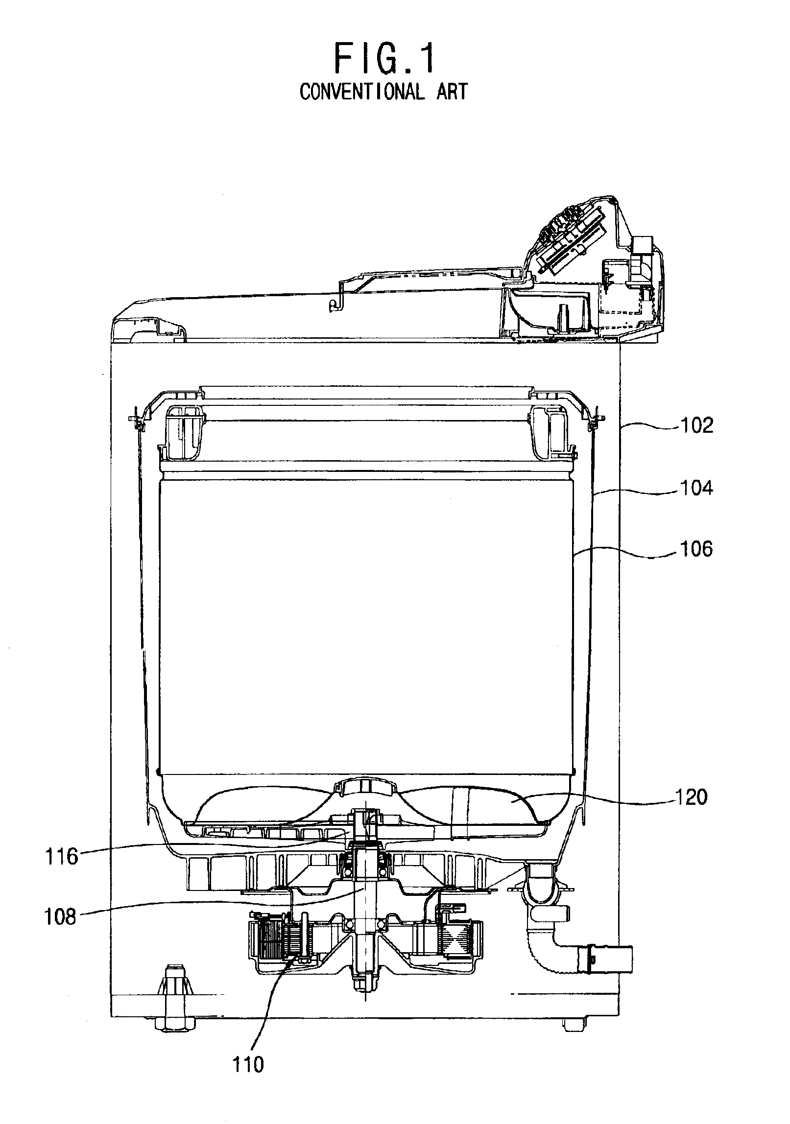
BACKGROUND OF THE INVENTION[0001]1. Field of the Invention[0002]The present invention relates to an inner tub for a washing machine, and particularly, to an inner tub for a washing machine by which a spin-drying of high speed can be made.[0003]2. Description of the Background Art[0004]Generally, washing machines can be divided into clutch driving type and direct drive type. Herein, the clutch driving type is a method for transmitting a driving force generated from a motor to a pulsator using a belt, pulley, and clutch, and the direct drive type is a method for driving a washing machine directly by connecting the driving motor to the washing motor.[0005]FIG. 1 is a cross-sectional view showing a direct drive type washing machine according to the conventional art.[0006]The conventional direct drive type washing machine comprises: a case 102 with an opened upper part; an outer tub 104, in which wash water is filled, supported inside the case 102; an inner tub 106 installed in the outer...

Claims


Application Information

Patent Timeline
IPC IPC(8): D06F37/12D06F37/00D06F49/02
CPCD06F37/12
Inventor LIM, HEE-TAECHANG, JAE-WONPARK, SEUNG-CHULPARK, GWAN-RYONG
Owner LG ELECTRONICS INC
Learn More