Liquid container

a liquid container and container body technology, applied in the field of liquid containers, can solve the problems of limited viscosity of liquid stored in the body, each function cannot be satisfactorily fulfilled, etc., and achieve the effect of low cost, easy construction, and not greatly reduced effect of effective volume of the tank

Inactive Publication Date: 2005-07-19
KOTOBUKI & CO LTD
View PDF10 Cites 17 Cited by
  • Summary
  • Abstract
  • Description
  • Claims
  • Application Information

AI Technical Summary

Benefits of technology

[0008]Since the supply mechanism is normally isolated from the tank by the valve, the tank is sealed and closed, so that the liquid in the tank does not leak. On the other hand, when the liquid in the tank is desired to be supplied to the supply mechanism, the liquid in the tank is pushed out to the supply mechanism by driving the drive mechanism, by which the valve is opened, so that the tank communicates with the supply mechanism. Thereby, the liquid in the tank is supplied to the supply mechanism, and can be supplied to an object through the tip end supply element. When the liquid in the tank is supplied to the supply mechanism and the pressure in the tank decreases, the valve returns to the normal state and is closed. The valve configured as described above can surely prevent even a liquid having a low viscosity from leaking. Also, since the supply mechanism is normally isolated from the tank, the dimensions etc. of the supply mechanism are not subject to any restriction by the viscosity of liquid.
[0009]The valve can be made of an elastic material, and have a plate portion which separates the supply mechanism from the tank, and is formed with a slit in a central portion of the plate portion. Thereby, the valve can be constructed easily at a low cost. Also, since the plate portion does not occupy the volume of tank greatly, the effective volume of the tank is not decreased greatly.

Problems solved by technology

However, because such a liquid leakage suppressing mechanism also serves as the coating liquid supply element, a problem is that since two opposing functions of supplying coating liquid and suppressing liquid leakage are provided by one single part, each of the functions cannot be fulfilled satisfactorily.
Therefore, another problem is that the viscosity of liquid stored in the body is limited by the inside diameter of the coating liquid supply element.

Method used


Image

  • Liquid container
  • Liquid container
  • Liquid container

Examples


Embodiment Construction

[0014]An embodiment of the present invention will now be described with reference to the accompanying drawings.

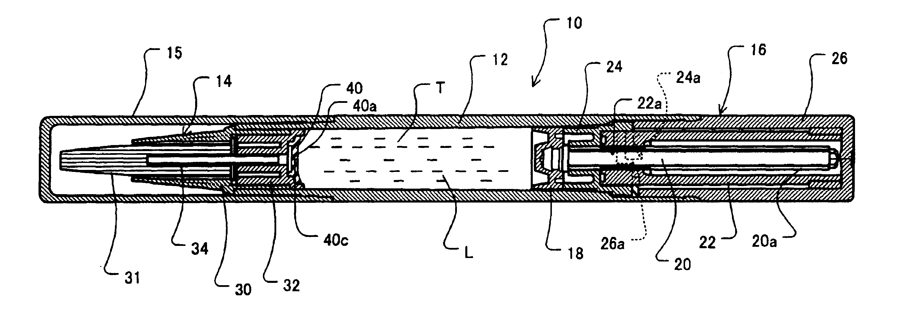
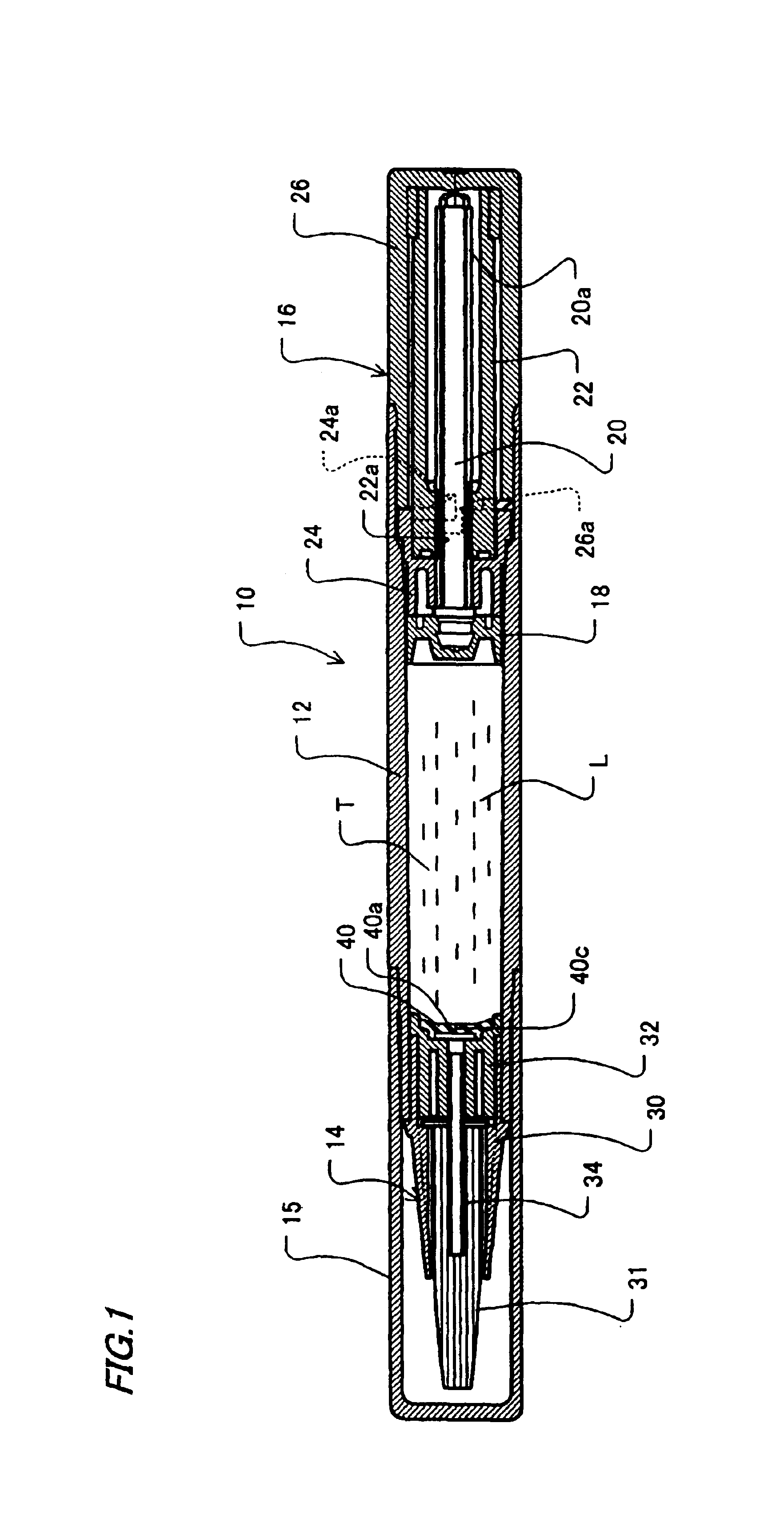
[0015]FIG. 1 is a longitudinal sectional view showing an embodiment of a liquid container in accordance with the present invention. In FIG. 1, a liquid container 10 includes a body 12 which defines a tank T for storing a liquid L such as an error-correcting liquid, writing ink, or cosmetic ink, a supply mechanism 14 which is connected to the tip end portion of the body 12, a drive mechanism 16 which is connected to the rear end portion of the body 12, and a cap 15 which is put detachably on the body 12 to cover the supply mechanism 14.

[0016]The drive mechanism 16 has a piston 18 which slides in the tank T, a piston rod 20 which is connected to the piston 18, extending rearward, and is formed with external threads 20a, a piston rod guide 22 which is formed with internal threads 22a threadably engaged with the external threads 20a of the piston rod 20, a ratchet 24 which is f...


PUM


Abstract

In a liquid container, the dimension of inside diameter of a liquid supply portion is not subject to any restriction, and also a liquid leakage suppressing mechanism that is not subject to any restriction by the viscosity of stored liquid is provided. A liquid container includes a body having a tank for storing a liquid; a supply mechanism which is connected to the tip end portion of the body and has a brush for supplying the liquid; and a drive mechanism for pushing out the liquid L in the tank T to the supply mechanism. A valve which is normally closed and can be opened only when the drive mechanism is operated is provided between the tank and the supply mechanism.

Description

BACKGROUND OF THE INVENTION[0001]1. Field of the Invention[0002]The present invention relates to a liquid container for storing a liquid having a relatively low viscosity such as lotion, error-correcting liquid, writing ink and cosmetic liquid. More particularly, it relates to a liquid container having an improved tightness and capable of preventing liquid leakage.[0003]2. Description of the Related Art[0004]Conventionally, as a liquid container of this type, a liquid applying device has been known which is provided with a coating liquid supply element, which is also operated as a liquid leakage suppressing mechanism, between an applier and a body to prevent the coating liquid from leaking into a cap due to expansion of gas intruding into the coating liquid or the interior of the body, drop, vibration, etc. (for example, see Japanese Patent Laid-Open No. 2002-165637). Particularly, this liquid leakage suppressing mechanism is comprised of the coating liquid supply elements consistin...

Claims


Application Information

Patent Timeline
Patent Type & Authority Patents(United States)
IPC IPC(8): A46B11/00B43L19/00A45D34/04A46B11/02B43K8/02B65D83/00
CPCA46B11/0079A46B2200/205
Inventor NOGUCHI, YOSHIO
Owner KOTOBUKI & CO LTD
Why Eureka
Try Eureka