Piezoelectric element, piezoelectric actuator and liquid ejection head incorporating the same

a piezoelectric actuator and actuator technology, applied in the direction of positive displacement liquid engine, device details, device details, etc., can solve the problem that the ability to respond to recently-growing demand cannot be achieved by mere use of piezoelectric elements of multi-layer structures, and achieve the effect of efficient deformation of vibration plates

Inactive Publication Date: 2005-07-19
SEIKO EPSON CORP
View PDF14 Cites 8 Cited by
  • Summary
  • Abstract
  • Description
  • Claims
  • Application Information

AI Technical Summary

Benefits of technology

[0025]In the above configurations, the degree of deformation of an upper layer piezoelectric substance stemming from supply of a drive signal is made greater

Problems solved by technology

However, characteristics capable of responding to recently-growing demand canno

Method used


Image

  • Piezoelectric element, piezoelectric actuator and liquid ejection head incorporating the same
  • Piezoelectric element, piezoelectric actuator and liquid ejection head incorporating the same
  • Piezoelectric element, piezoelectric actuator and liquid ejection head incorporating the same

Examples


second embodiment

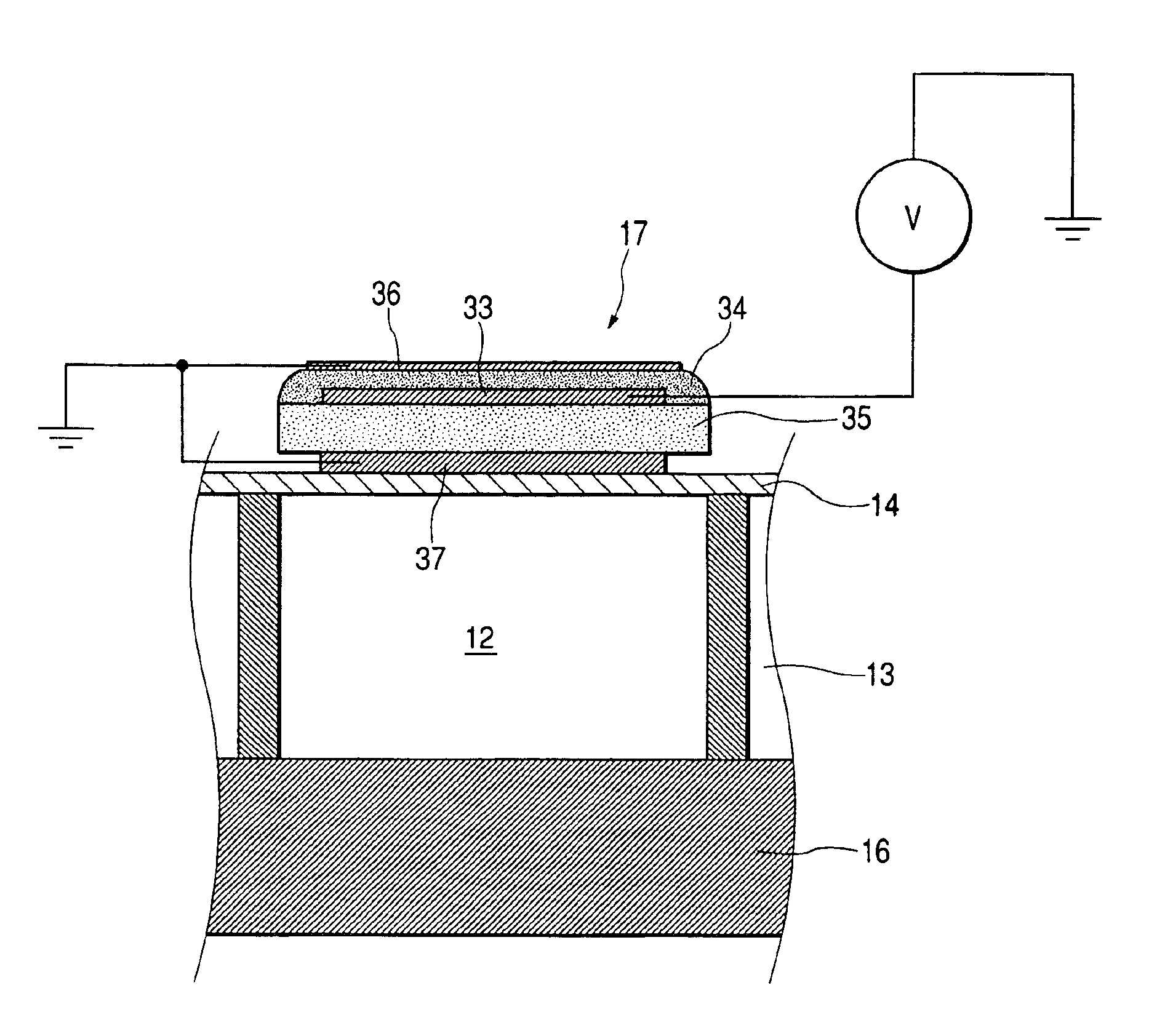
[0113]However, the invention is not limited to such a configuration. For instance, the upper common electrode 36 is electrically insulated from the lower common electrode 37. The upper common electrode 36 may be set to a common potential (e.g., an earth potential), whereas the lower common electrode 37 may be set to a bias potential which is higher than the common potential by a predetermined potential. By such a configuration, the electric field imparted to the lower piezoelectric substance 35 becomes weaker than the electric field imparted to the upper layer piezoelectric substance 34 by only an amount corresponding to a difference between the bias potential and the common potential. Put another way, the electric field imparted to the upper layer piezoelectric substance 34 becomes stronger than the electric field imparted to the lower layer piezoelectric substance 35 by the potential difference. A second embodiment in which the piezoelectric element is configured in the previously...

first embodiment

[0114]As shown in FIGS. 12A and 12B, in the embodiment, the conduction member 47 (see FIG. 9F) described in connection with the first embodiment is not provided, and the upper common electrode 36 and the lower common electrode 37 are electrically insulated from each other. The upper common electrode 36 is provided with a common potential supplying section 36a to be used for supplying a common potential to the upper common electrode 36, and the lower common electrode 37 is provided with a bias potential supplying section 37a to be used for supplying a bias potential V′. The common potential supplying section 36a and the bias potential supplying section 37a can be provided at arbitrary positions within the upper common electrode 36 and the lower common electrode 37. In the embodiment, as shown in FIG. 12B, the common potential supplying section 36a is provided adjacent to a portion of the upper common electrode 36 corresponding to the conduction area 42a of the embodiment, and the bia...


PUM


Abstract

A first common electrode is fixed at a predetermined potential. A first piezoelectric layer is laminated on the first common electrode and has a first deformability with respect to a predetermined voltage. A drive electrode is laminated on the first piezoelectric layer, to which a drive signal is supplied externally. A second piezoelectric layer is laminated on the drive electrode and having a second deformability with respect to the predetermined voltage which is larger than the first deformability. A second common electrode is laminated on the second piezoelectric layer and to be fixed at the predetermined potential.

Description

BACKGROUND OF THE INVENTION[0001]The invention relates to a piezoelectric element which becomes deformed upon receipt of a supplied drive signal, to a piezoelectric actuator and a liquid ejecting head incorporating the piezoelectric element as a drive source.[0002]A piezoelectric element is formed from piezoelectric ceramics or a piezoelectric macromolecular film utilizing a high molecular compound and becomes deformed upon receipt of supplied electric energy. Here, the piezoelectric ceramics is formed by compacting and sintering metal oxide powder, such as BaTiO3, PbZrO3, PbTiO3, which are piezoelectric materials and exhibit a piezoelectric effect. The piezoelectric element has been in widespread use as a drive element for, e.g., a liquid ejecting head, a micropump, and a sounding body (a speaker or the like). Here, the liquid ejecting head ejects a droplet from a nozzle orifice by inducing pressure fluctuations in a liquid stored in a pressure chamber. The liquid ejecting head is ...

Claims


Application Information

Patent Timeline
IPC IPC(8): B41J2/14B41J2/045B41J2/055F04B43/04H01L41/083H01L41/09
CPCB41J2/14233H01L41/0973H10N30/2047
Inventor JUNHUA, CHANG
Owner SEIKO EPSON CORP
Why Eureka
Try Eureka