Combustion apparatus

a technology of combustion apparatus and spherical gas, which is applied in the direction of combustion control, combustion types, lighting and heating apparatus, etc., can solve the problems of poor heat generation efficiency, mist particle accumulation of fuel, and loss of fuel, and achieve accurate control of the spherical gas spray rate, the effect of simplifying the structur

Inactive Publication Date: 2005-07-19
NORITZ CORP
View PDF29 Cites 25 Cited by
  • Summary
  • Abstract
  • Description
  • Claims
  • Application Information

AI Technical Summary

Benefits of technology

[0014]An object of the present invention made in view of the problems and drawbacks mentioned above is therefore to provide an advanced combustion apparatus that is simplified in structure, but is nevertheless possible to accurately regulate the sprayed rate of a fuel to ensure complete combustion.

Problems solved by technology

The minor portion is thus prone to be cooled to cause aggregation of mist particles of fuel, being discharged as an unburnt waste of fuel.
Therefore, such a minor portion sprayed from nozzle 205 but not burnt will cause a loss of fuel.
An actual amount of heat will be short of the required amount of heat to be generated, resulting in a poor efficiency in generation of heat.
Consequently, the flow rate at which the remainder of fuel stream flows back through the return channel will become unreliable.
It has been somewhat difficult for the related art apparatus 201 to precisely regulate the spraying rate of fuel, failing to stabilize the condition of combustion state.

Method used


Image

  • Combustion apparatus
  • Combustion apparatus
  • Combustion apparatus

Examples


Embodiment Construction

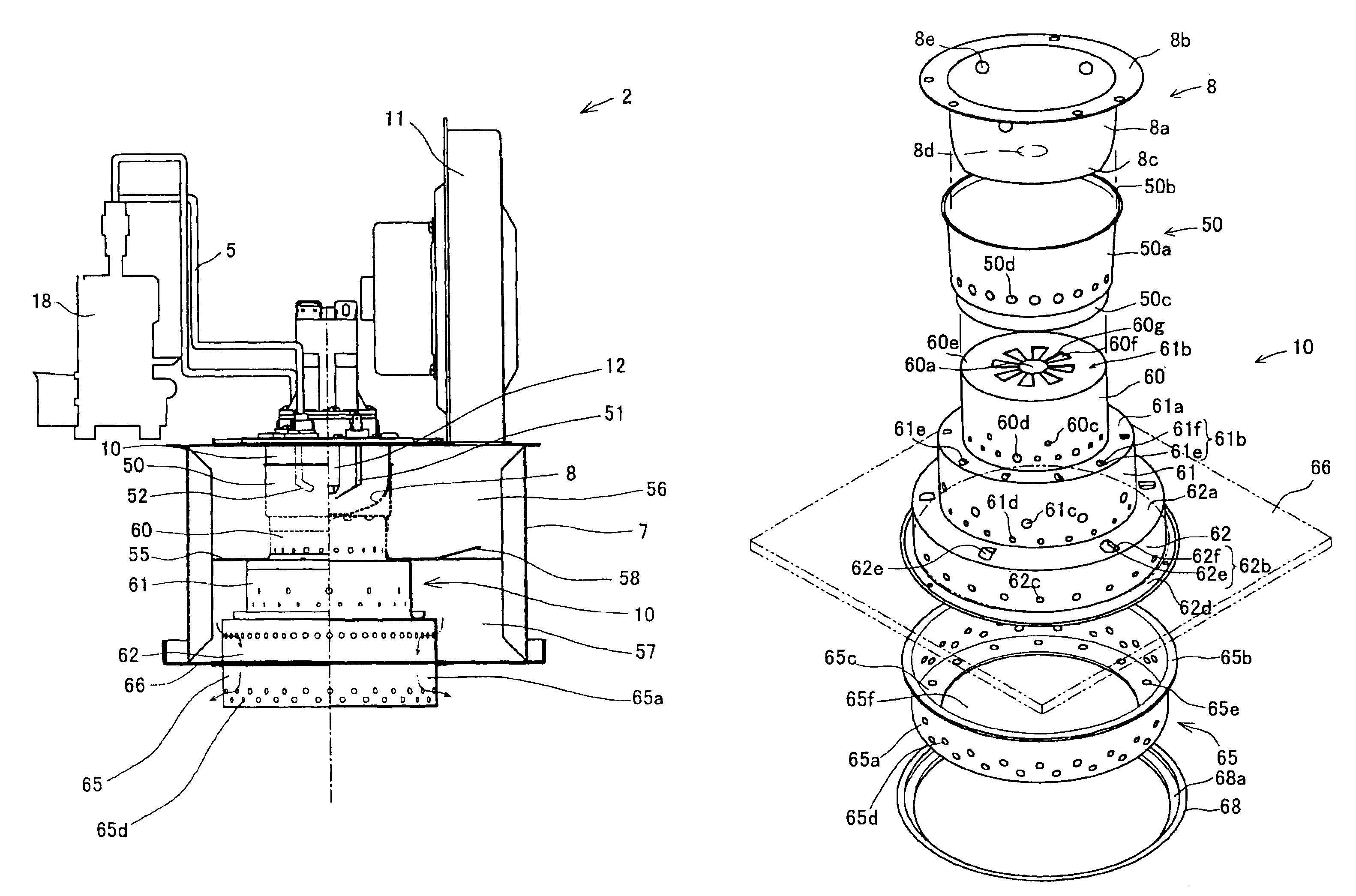
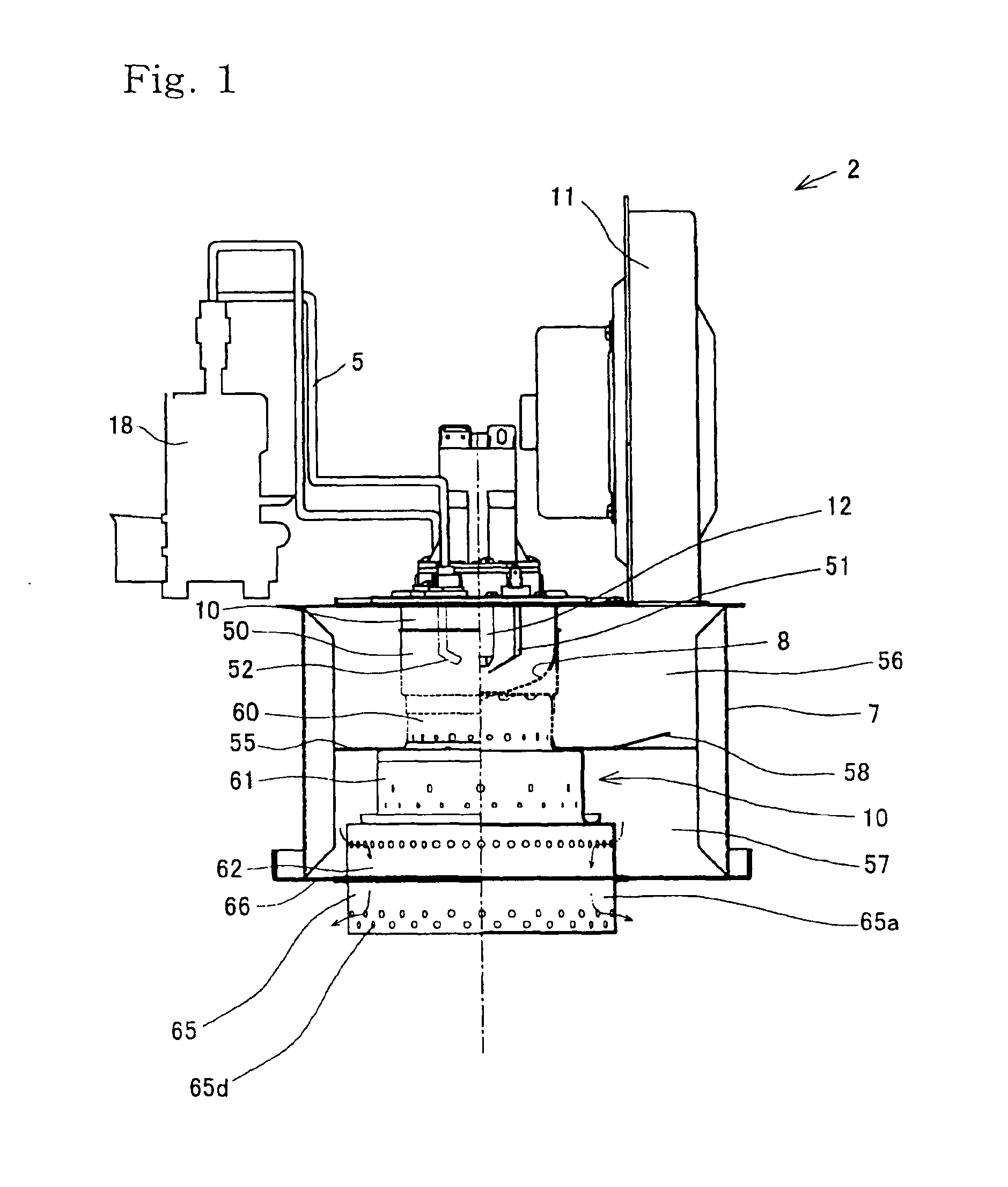
[0082]In FIG. 1, a combustion apparatus of a first embodiment is generally denoted at the reference numeral 2. This apparatus 2 comprises a nozzle block 8 having an end opened in a casing 7, and a combustion chamber 10 is attached to the end of nozzle block 8. A fan or blower 11 mounted on the casing 7 will operate to feed the ambient air into the combustion chamber 10. A fuel spraying nozzle (as the spraying means) 12 is installed in the nozzle block 8 in order to spray a fuel towards and into the combustion chamber 10.

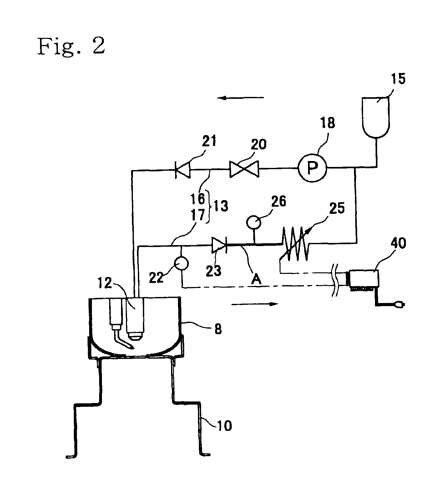
[0083]The spraying nozzle 12 has a spray mouth (not shown) for jetting the fuel. An internal feed path (not shown) and an internal return path (not shown) leading to or starting back from the spray mouth are formed in or for the nozzle 12. Thus, the fuel spraying nozzle 12 will operate to jet a portion of the fuel that is being fed from the outside through the feed canal. The remainder of said fuel will be left unsprayed to subsequently flow back through the return c...


PUM


Abstract

A combustion apparatus 2 has an anti-spreading member 65 disposed below a combustion chamber 10. This anti-spreading member 65 is composed of a generally cylindrical main body 65a, an outer flange 65b and an inner flange 65c, these flanges being formed at and integral with the opposite ends of the main body 65a, respectively. A controller 40 for regulating the operation of this apparatus 2 is designed to preheat the anti-spreading member 65 at a heat generation rate ‘q’ lower than the required heat generation rate ‘Q’, before the apparatus starts its normal operation to burn a fuel.

Description

BACKGROUND OF THE INVENTION[0001]1. Field of the Invention[0002]The present invention relates to a combustion apparatus for burning a liquid fuel.[0003]2. Description of Related Art[0004]Some combustion apparatuses known in the art are of the type as disclosed in Patent Laying-Open Gazette No. 10-227453. A fuel spraying nozzle incorporated in this apparatus operates to blow a fuel mist to be burnt continuously. This nozzle is of the so-called return type that has an internal return path such that a portion of the fuel supplied from a fuel tank will flow back toward the tank through the internal return path and a return channel provided out of the nozzle.[0005]FIG. 11 is a scheme of the related art combustion apparatus 201 that incorporates the return type nozzle 205 for spraying the fuel and a combustion chamber 204 for burning the fuel sprayed by the nozzle 205.[0006]The fuel spraying nozzle 205 built in this apparatus 201 has a spray mouth for jetting a fuel mist. A fuel channel (...

Claims


Application Information

Patent Timeline
Patent Type & Authority Patents(United States)
IPC IPC(8): F23D1/00F23N1/02F23N1/00F23C6/04F23C7/00F23D11/26F23D11/30
CPCF23C6/045F23C7/004F23D11/26F23D11/30F23N1/022F23C2900/06041F23N2027/02F23N2033/08F23N2035/14F23N2035/30F23N2037/10F23N2227/02F23N2233/08F23N2235/14F23N2235/30F23N2237/10
Inventor NAKAMURA, YUTAKAHASEGAWA, HIROKIHARA, HITOSHI
Owner NORITZ CORP
Why Eureka
Try Eureka