Computer telephony system using multiple hardware platforms to provide telephony services

a technology of telephony services and hardware platforms, applied in the field of computer telephony systems, can solve the problems of not being able unable to provide required capabilities, and unable to meet the needs of changing market requirements and new hardware capabilities, so as to protect investment in application code, simplify application development, and ensure the effect of application scal

Inactive Publication Date: 2005-07-19
VOIP DYNAMIC
View PDF14 Cites 23 Cited by
  • Summary
  • Abstract
  • Description
  • Claims
  • Application Information

AI Technical Summary

Benefits of technology

[0006]This invention pertains to a computer telephony system having a multi-platform architecture capable of delivering a high degree of scaleability, extensibility, portability, and configurability. The architecture provides a layer of abstraction between the application software and hardware associated with each platform. The architecture is useful in delivering a variety of computer telephony services including voice, data, and fax services, as well as video and other multi-media services. Also, the architecture can be used with different computer telephony platforms including POTS, IP, and wireless telephony. The flexibility of such a system facilitates delivery of a wide range of services over a wide range of platforms.

Problems solved by technology

Development of applications sometimes does not keep pace with evolving market requirements and new hardware capabilities.
Due to the lag in application development, required capabilities may not be available when the user desires them.
Consequently, existing messaging systems and applications may be rendered obsolete by new hardware platforms.
The time and cost of application and firmware redevelopment can undermine the price and performance gains of the new hardware.
The challenge is to quickly deliver new messaging platforms based on those technologies.

Method used


Image

  • Computer telephony system using multiple hardware platforms to provide telephony services
  • Computer telephony system using multiple hardware platforms to provide telephony services
  • Computer telephony system using multiple hardware platforms to provide telephony services

Examples


Embodiment Construction

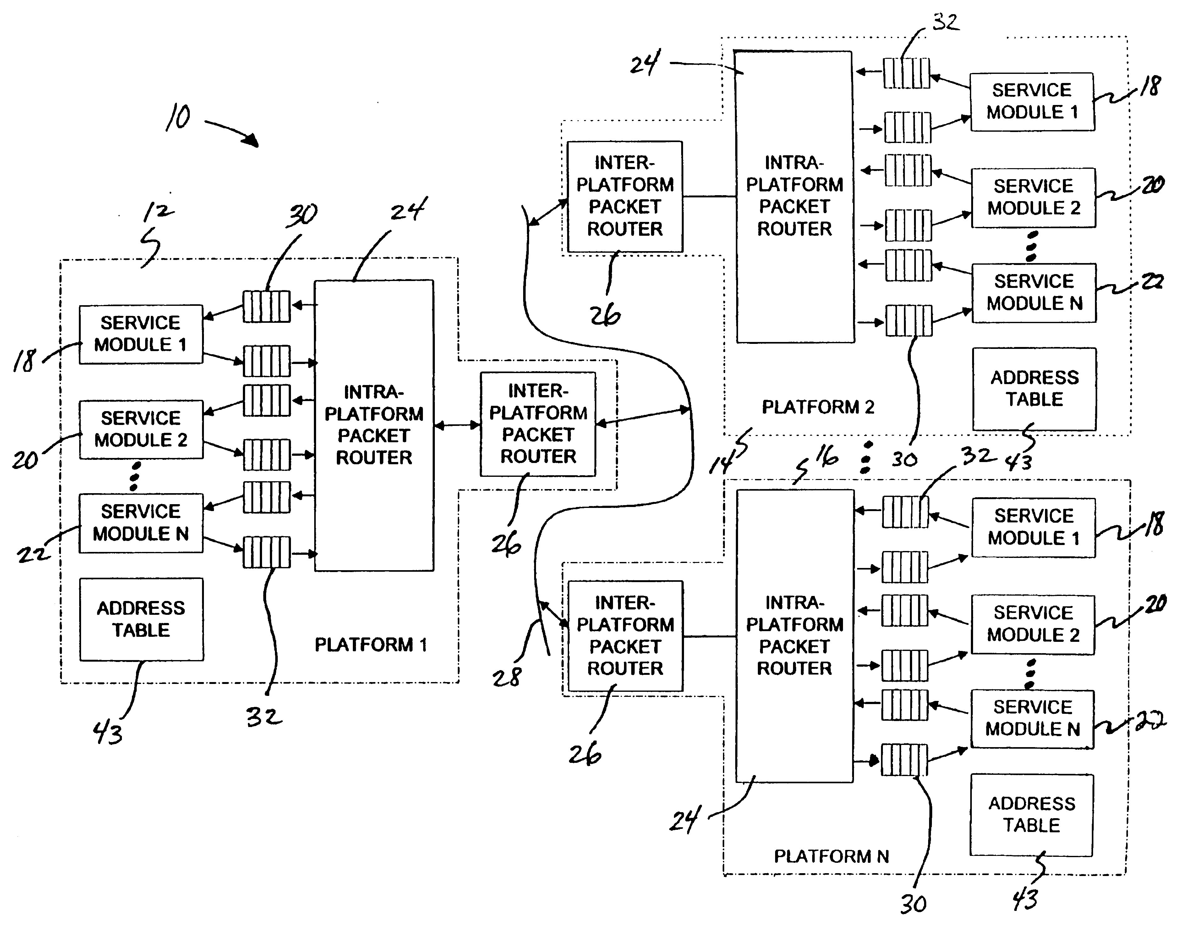
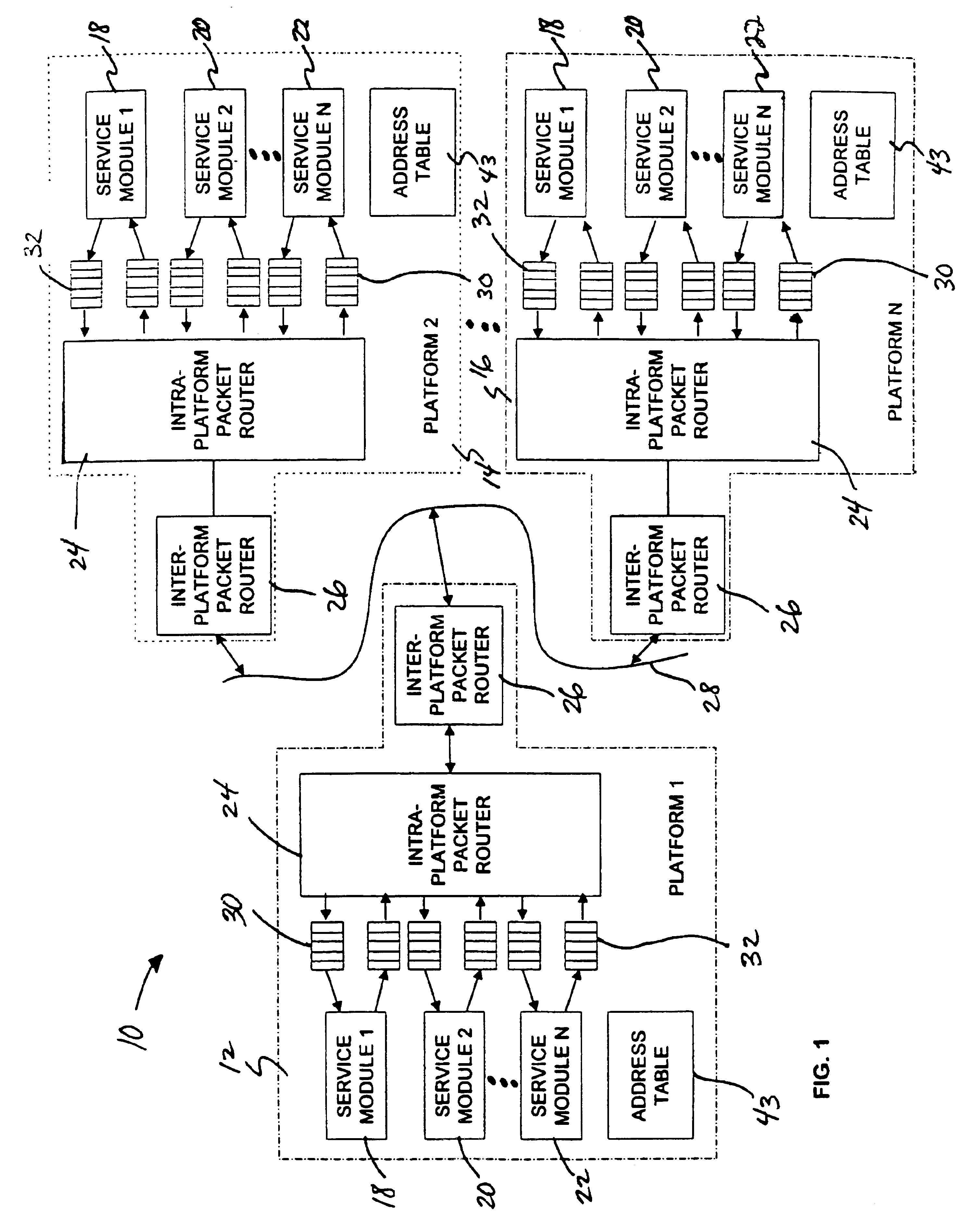
[0029]FIG. 1 is a functional block diagram of a computer telephony system 10 having a multi-platform architecture. As shown in FIG. 1, computer telephony system 10 includes computer telephony platforms 12, 14, 16. Each platform 12, 14, 16 includes service modules 18, 20, 22, an intra-platform packet router 24, an inter-platform packet router 26, and a processor and associated hardware and software for implementing modules 18, 20, 22, router 24, and router 26. Platforms 12, 14, 16 comprise computer workstations, hardware components controlled by a common processor, or systems integrating both.

[0030]Platforms 12, 14, 16 may be scalable to include additional service modules. Service modules 18, 20, 22 communicate with a platform processor via a host bus, e.g., ISA, PCI, or VME. In some cases, service modules 18, 20, 22 on a common platform may communicate with one another via private board interconnects. Platforms 12, 14, 16 are dynamically interconnected for communication with one ano...


PUM


Abstract

A computer telephony system includes a multi-platform architecture that provides a layer of abstraction between application software and hardware associated with a platform. According to this architecture, service modules residing on different platforms access computer telephony resources to facilitate performance of a variety of computer telephony services. Although local access to such resources is governed by diverse, platform-dependent protocols, the service modules communicate with one another according to a common, platform-independent protocol. In this manner, cross-platform communication is abstracted to isolate system software and firmware from hardware-based platform dependencies. Instead of threaded drivers creating a persistent, dedicated link with resources, communication can be accomplished via a common, platform-independent message packet protocol.

Description

[0001]This is a continuation-in-part of U.S. patent application Ser. No 09 / 260,299, to Ortiz et al., filed Mar. 2, 1999, abandoned Sep. 27, 2002. Priority is claimed from U.S. patent application Ser. No. 09 / 260,299 and U.S. Provisional Application Ser. No. 60 / 077,793, filed Mar. 12, 1998, the provisional application expired.TECHNICAL FIELD[0002]This invention relates to computer telephony systems that use multiple hardware platforms to provide telephony services.BACKGROUND INFORMATION[0003]Computer telephony (CT) systems manage the flow of electronic messages. Such messages include voice, data, and facsimile information, as well as video and other multi-media information. Computer telephony systems receive messages via the public telephone network or a private enterprise network, and may make use of POTS, IP, and wireless telephony technology. Computer telephony systems provide an array of telephony services.[0004]To deliver services that can handle fax, voice, and data messaging, a...

Claims


Application Information

Patent Timeline
Patent Type & Authority Patents(United States)
IPC IPC(8): H04L12/28H04L12/56H04L29/06H04M3/42H04Q3/00
CPCH04M3/42323H04M7/0018H04Q3/0045H04L65/1043H04L65/1069H04L29/06027H04L65/1101
Inventor ORTIZ, LUISCASSIDY, KEVIN J.
Owner VOIP DYNAMIC
Why Eureka
Try Eureka