Electronic systems testing employing embedded serial scan generator

a technology of embedded serial scan and generator, which is applied in the direction of electric/magnetic computing, instruments, analogue processes for specific applications, etc., can solve the problems of difficult to achieve complex designs, low detection accuracy, and insufficient method to provide a high level of detectable fault coverage. , to achieve the effect of reducing the time-to-market of user manufacturers, reducing application development time, and high capital-cos

Inactive Publication Date: 2005-07-19
TEXAS INSTR INC
View PDF2 Cites 58 Cited by
  • Summary
  • Abstract
  • Description
  • Claims
  • Application Information

AI Technical Summary

Benefits of technology

[0028]Among the objects of the present invention are to provide improved emulation, simulation and testability architectures and methods which provide visibility and control without physical probing or special test fixtures; to provide improved emulation, simulation and testability architectures and methods which are applicable to critical components of system designs to support test and integration of both hardware and software; to provide improved emulation, simulation and testability architectures and methods that are a viable alternative to high capital-cost test equipment and systems; to provide improved emulation, simulation and testability architectures and methods which integrate access to sophisticated operations in hardware emulation, fault emulation, simulation and built-in test; to provide improved emulation, simulation and testability architectures and methods which apply hardware and software visibility and control to reduce application development time and thus reduce the user manufacturer's time-to-market on new products; and to provide improved emulation, simulation and testability architectures and methods to leverage hierarchical partitioning and automatically generate reusable tests for related chips and systems.

Problems solved by technology

Diminished physical access is an unfortunate consequence of denser designs and shrinking interconnect pitch.
This basic necessity is difficult to achieve for complex designs without taking testability into account in the logic design phase, so that automatic test equipment can test the product.
For very large systems this method proves inadequate in providing a high level of detectable fault coverage.
Another problem in large designs is the long time and substantial expense involved.
Without a proactive testability, simulation and emulation approach, a large amount of subsequent design time is expended on test pattern creation and grading.
The advances in IC design, for example, are accompanied by decreased internal visibility and control, reduced fault coverage and reduced ability to toggle states, more test development and verification problems, increased complexity of design simulation and continually increasing cost of CAD (computer aided design) tools.
In the board design the side effects include decreased register visibility and control, complicated debug and simulation in design verification, loss of conventional emulation due to loss of physical access by packaging many circuits in one package, increased routing complexity on the board, increased costs of design tools, mixed-mode packaging, and design for produceability.
In application development, some side effects are decreased visibility of states, high speed emulation difficulties, scaled time simulation, increased debugging complexity, and increased costs of emulators.
Production side effects involve decreased visibility and control, complications in test vectors and models, increased test complexity, mixed-mode packaging, continually increasing costs of automatic test equipment even into the 7-figure range, and tighter tolerances.

Method used


Image

  • Electronic systems testing employing embedded serial scan generator
  • Electronic systems testing employing embedded serial scan generator
  • Electronic systems testing employing embedded serial scan generator

Examples


Embodiment Construction

[0065]The coassigned, incorporated applications and patents cited above U.S. patent application Ser. No. 07 / 846,459, U.S. Pat. No. 5,535,331, U.S. Pat. No. 6,085,336, U.S. Pat. No. 5,329,471, U.S. patent application Ser. No. 07 / 949,757 and U.S. Pat. No. 5,805,792 have identical drawings to each other and disclose emulation, simulation and testability circuitry, devices, systems and methods as well as principles and terminology that provide an exemplary context for the detailed description of the circuitry, devices, systems and methods disclosed herein. Accordingly, reference numerals correspond as much as possible in the present further drawings with the numerals of the just-listed coassigned, incorporated applications.

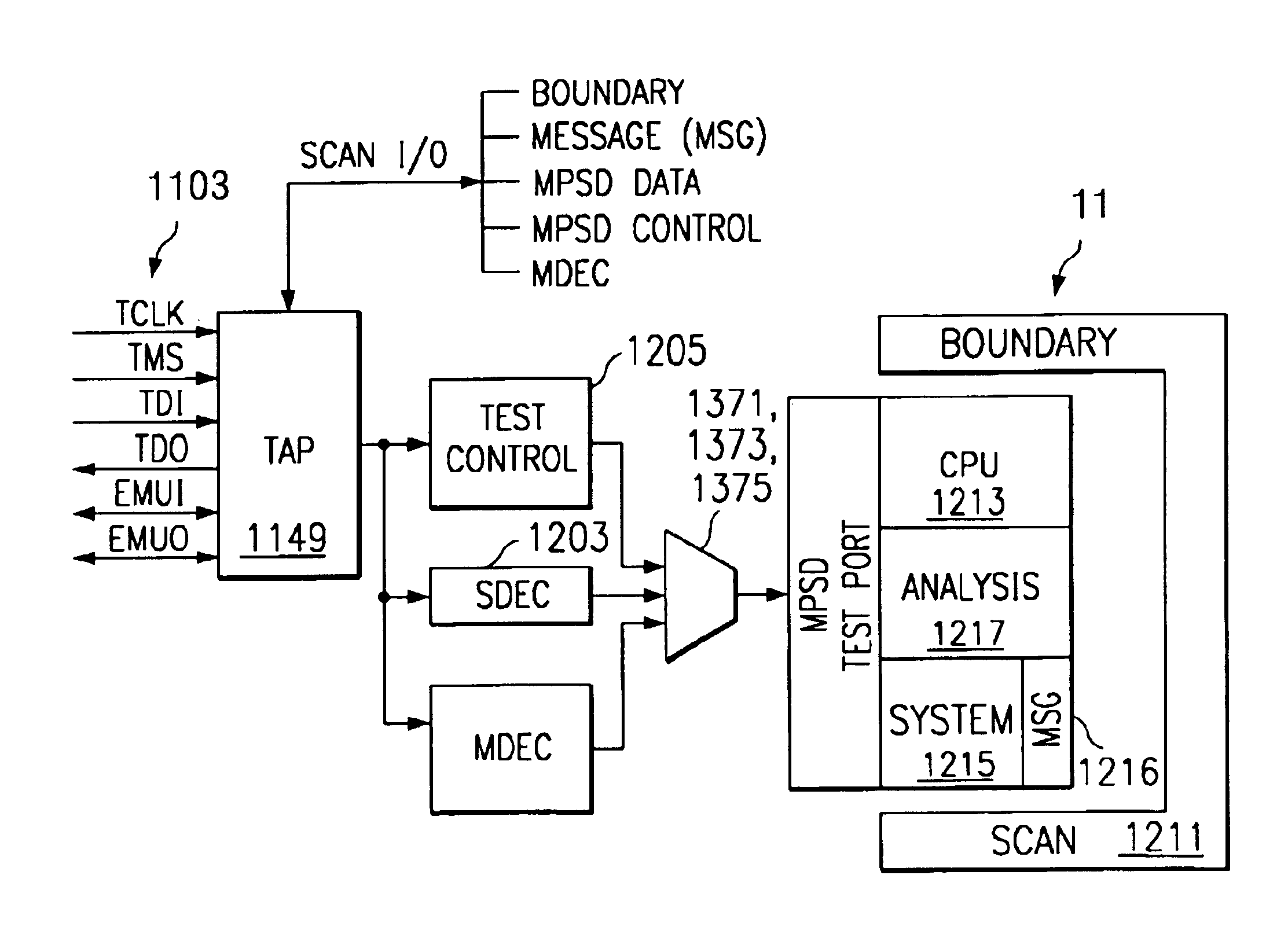
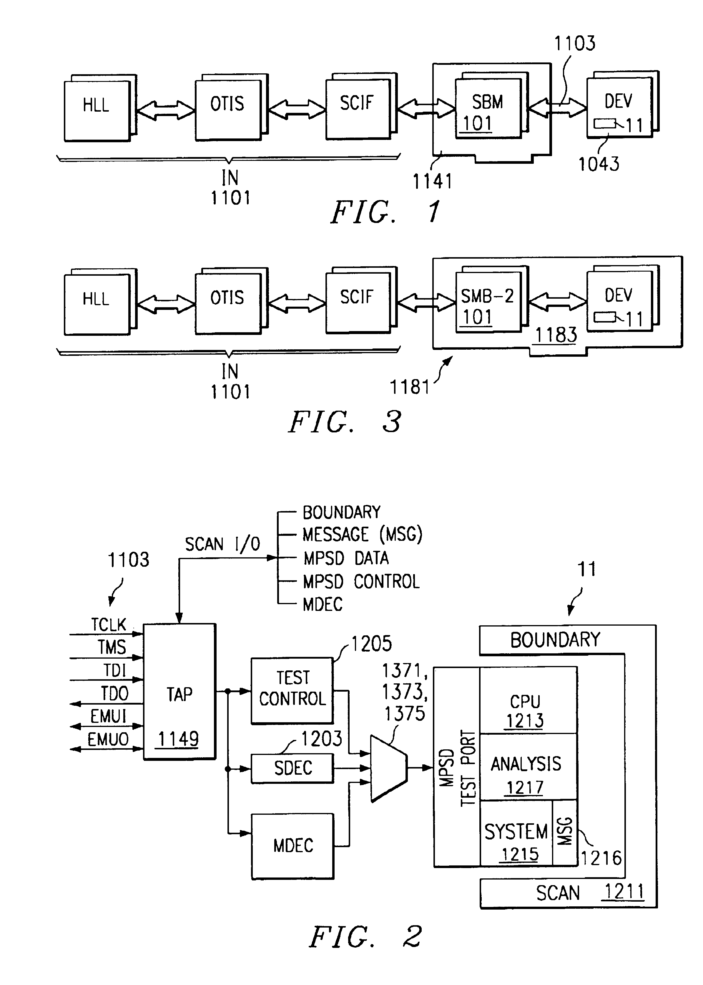
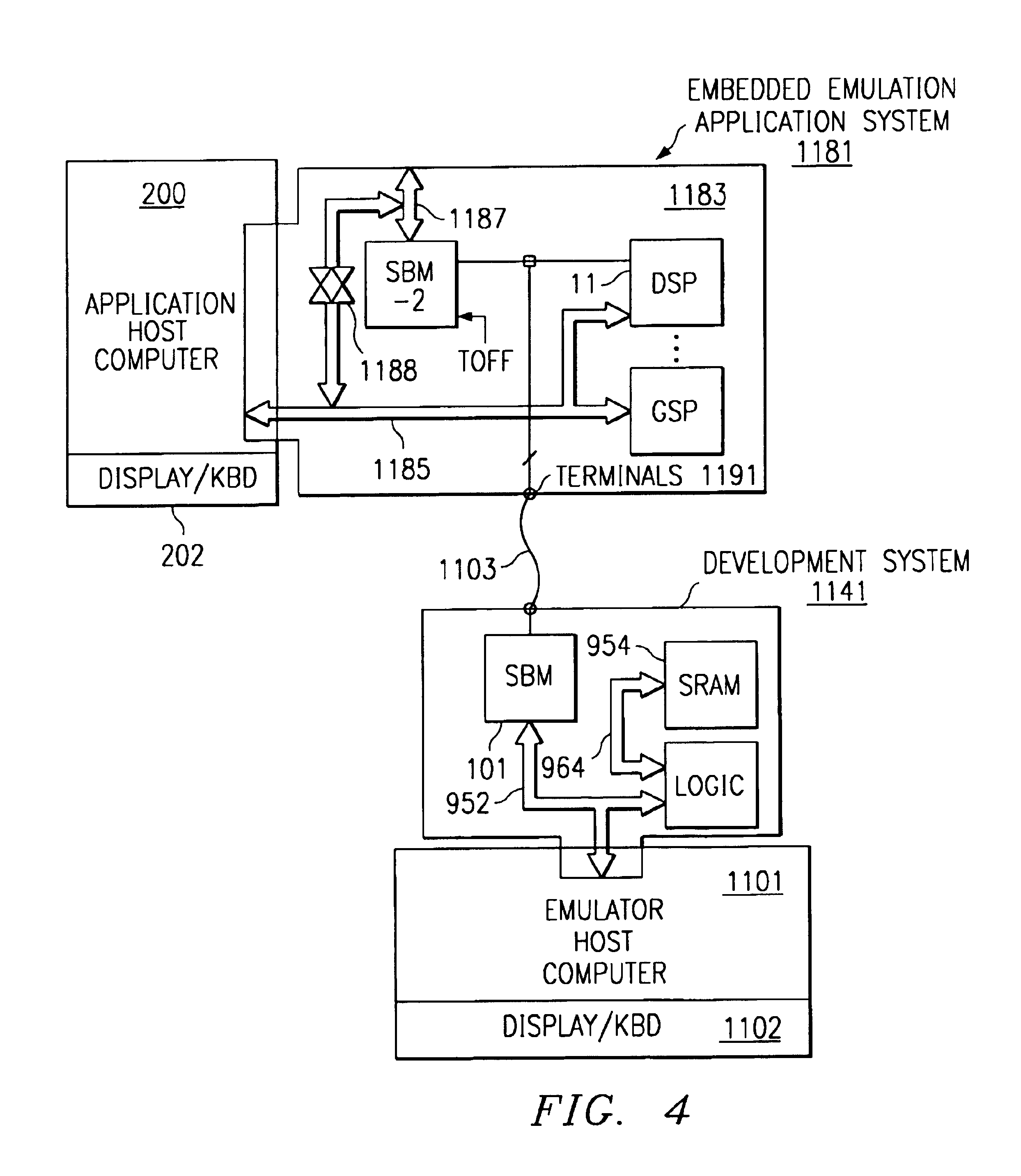
[0066]For example, in FIG. 1 of the present application, and with reference to FIGS. 44 and 45 of said incorporated applications, emulation-simulation-test host computer 1101 has high level language HLL software including an operational target interface system OTIS an...


PUM


Abstract

An electronic system includes electronic circuitry to be tested having serial scan shift register latches, and a serial scan generator embedded in the electronic system upon manufacture and connected to the serial scan shift register latches of the electronic circuitry to facilitate testing. The electronic system may consist of a single printed circuit board mounting both the electronic circuitry and the serial scan generator. The electronic system may consist of a single semiconductor chip carrier mounting both the electronic circuitry and the serial scan generator, are both mounted on said single semiconductor chip carrier. The electronic system may further include a detachable second serial scan generator. The serial scan generator preferably operates slower than the detachable second serial scan generator. The electronic system may further include a disabling terminal disabling the serial scan generator upon attachment of the detachable second serial scan generator.

Description

CROSS-REFERENCE TO RELATED APPLICATIONS[0001]This application is a divisional of U.S. patent application Ser. No. 07 / 851,232 filed on Mar. 13, 1992, now U.S. Pat. No. 5,684,721, which is a continuation of U.S. patent application Ser. No. 07 / 401,198 filed Aug. 28, 1989 and now abandoned.[0002]This application is a continuation in part of the following applications which are hereby incorporated herein by reference:[0003]U.S. patent application Ser. No. 07 / 415,375 filed Sep. 27, 1989 now U.S. Pat. No. 5,140,687 entitled “DATA PROCESSING APPARATUS WITH SELF-EMULATION CAPABILITY”; which is a continuation of U.S. patent application Ser. No. 06 / 948,337 filed Dec. 31, 1996, and now abandoned; which is a continuation-in-part of U.S. patent application Ser. No. 06 / 790,299 filed Oct. 22, 1985 and now abandoned.[0004]U.S. patent application Ser. No. 07 / 440,454 filed Nov. 21, 1989 entitled “MICROCOMPUTER HAVING A REAL-TIME EMULATION MODE AND SYSTEM FOR EMULATING THE SAME” and now abandoned; whic...

Claims


Application Information

Patent Timeline
Patent Type & Authority Patents(United States)
IPC IPC(8): G06F11/26G06F11/36
CPCG06F11/261G06F11/3656
Inventor SWOBODA, GARY L.HOAR, HENRY R.COOMES, JOSEPH A.
Owner TEXAS INSTR INC
Why Eureka
Try Eureka