Tissue treatment by normothermic heating

a tissue treatment and normothermic heating technology, applied in the direction of contraceptive devices, bandages, infusion syringes, etc., can solve the problems of increasing morbidity, inhibiting wound healing, and slowing cellular functions and biochemical reactions, so as to prevent wound death, increase the capacity of holding moisture, and reduce the effect of aging

Inactive Publication Date: 2005-07-26
3M INNOVATIVE PROPERTIES CO +1
View PDF98 Cites 58 Cited by
  • Summary
  • Abstract
  • Description
  • Claims
  • Application Information

AI Technical Summary

Benefits of technology

[0019]The effects of hypothermia on healing are well known. A number of regulatory systems within a human are affected, such as the immune system and coagulation, with both platelet function as well as the clotting cascade affected. Patients with hypothermic wounds experience more infections which are more difficult to treat, have increased bleeding times and have been shown to require more transfusions of blood. All of these complications increase morbidity and the cost of patient care and, to a lesser extent, increase the likelihood of mortality.
[0024]The present invention anticipates that the controller is able to control both the temperature and the duration of the application of heat. This control may extend from manual to fully automatic. Manual control anticipates the controller maintaining the heater temperature at an operator-selected temperature for as long as the operator leaves the heater on. More automatic modes provide the operator an ability to enter duty cycles, to set opt t as well as to define therapy cycles and therapeutic sequences. As used herein, a duty cycle is a single on cycle when heating of the heater is occurring, measured from the beginning of the on cycle to the end of that on cycle. A heater cycle is a single complete on / off cycle measured from the beginning of a duty cycle to the beginning of the next duty cycle. Consequently, a duty cycle may also be represented in a percentage of, or as a ratio of the time on over the time off. A plurality of heater cycles are used to maintain heater temperature around a selectable temperature set point during a therapy cycle which is defined as an “on” period, composed of a plurality of heater cycles, and an “off” period equivalent to remaining off for an extended period of time. A therapeutic sequence, as used herein, is a longer period of time usually involving a plurality of therapy cycles spread out over an extended period of time, the most obvious being a day in length. The present invention anticipates the use of any period of time as a therapeutic sequence and involving one, or more than one therapy cycles.
[0029]The barrier layer may include a pocket adapted to receive an active heater. An alternate form of the invention provides for the transport of heated air from a remote heat source to the wound treatment volume. In the active heater embodiments a thermostat and / or a pressure-activated switch may be used to control the heating effects of the heater. Passively heated embodiments are contemplated as well. These passive versions of the device include the use of thermally insulating coverings which retain body heat within the treatment volume. These reflectors or insulators may be placed in a pocket formed in the barrier layer. Each of these heated embodiments promote wound healing by maintaining the wound site at a generally elevated, but controlled, temperature.
[0033]The present invention differs from infrared lamps in two ways. First, the present invention includes a dome over the wound that is relatively impermeable to water vapor transmission. After application of the bandage, moisture from the intact skin or wound evaporates, and air within the dome quickly reaches 100% relative humidity. The interior of the present invention is now warm and humid. For example, a 2.5 square inch bandage at 28° C. requires only 0.0014 g of water to reach saturation. When the air is thus saturated, no further evaporation can occur and, therefore, no dying of the wound can occur. This equilibrium will be maintained as long as the bandage is attached to the patient.
[0034]When heat is provided by the preferred embodiment of the present invention, the absolute amount of water needed to reach 100% relative humidity is slightly increased since warm air has a greater capacity for holding moisture. However, the air within the dome of the bandage still reaches water vapor saturation very quickly, and no further evaporation occurs. For example, a 2.5 square inch bandage of the present invention at 38° C. requires only 0.0024 g of water to reach saturation. Excess moisture is absorbed by the foam ring, but still is retained within the bandage. The enclosed dome design maintains 100% humidity over the wound which also prevents evaporation due to the heat. As long as the humidity is retained within the bandage, heating therapy could theoretically be continued indefinitely without causing the wound to dry. In contrast, when using infrared lamps, the wounds are open and exposed to the environment. The result is excessive drying of the wound, increasing tissue damage.
[0036]At the low (normothermic) operating temperatures of the present invention, the heat transfer to the skin is minimal. The low wattage heater, the inefficiencies of the heat transfer into the tissue, the thermal mass of the tissue and the blood flow (even if markedly reduced), all prevent the wound temperature from reaching the heater temperature. Hypothermic wound tissue is warmed as a result of “migration” of the body's core temperature zone toward the local wound area.

Problems solved by technology

This skin hypothermia slows cellular functions and biochemical reactions, inhibiting wound healing.
All of these complications increase morbidity and the cost of patient care and, to a lesser extent, increase the likelihood of mortality.

Method used


Image

  • Tissue treatment by normothermic heating
  • Tissue treatment by normothermic heating
  • Tissue treatment by normothermic heating

Examples


Embodiment Construction

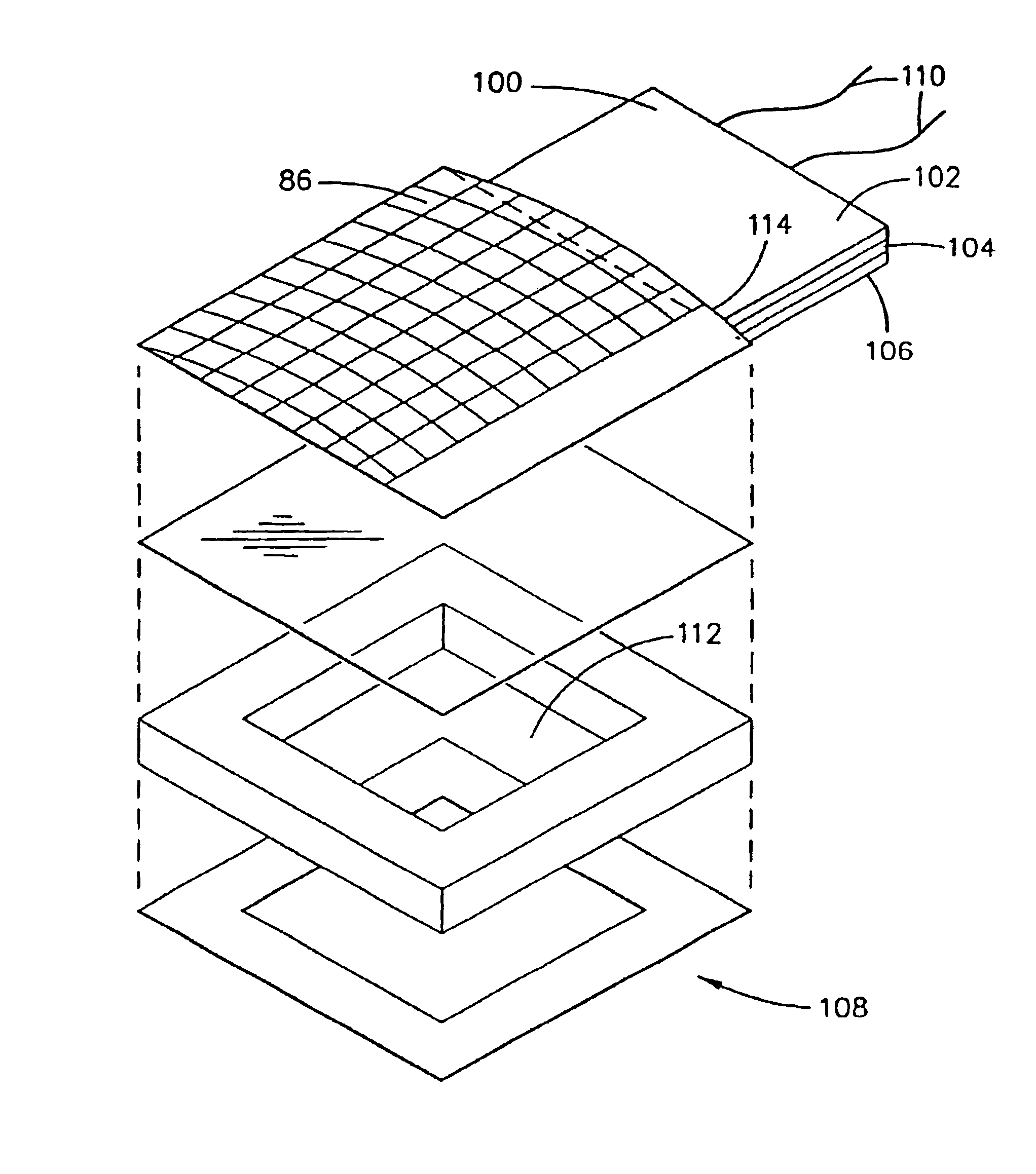
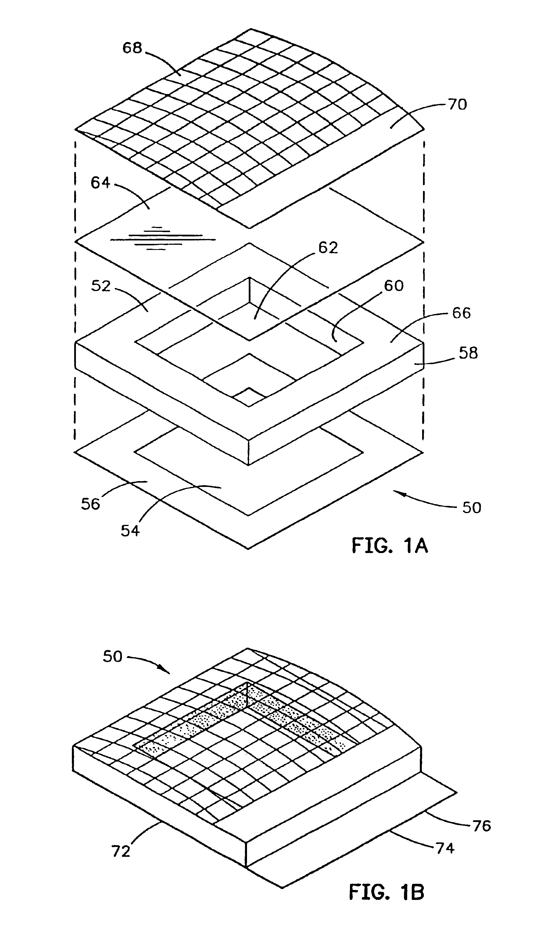
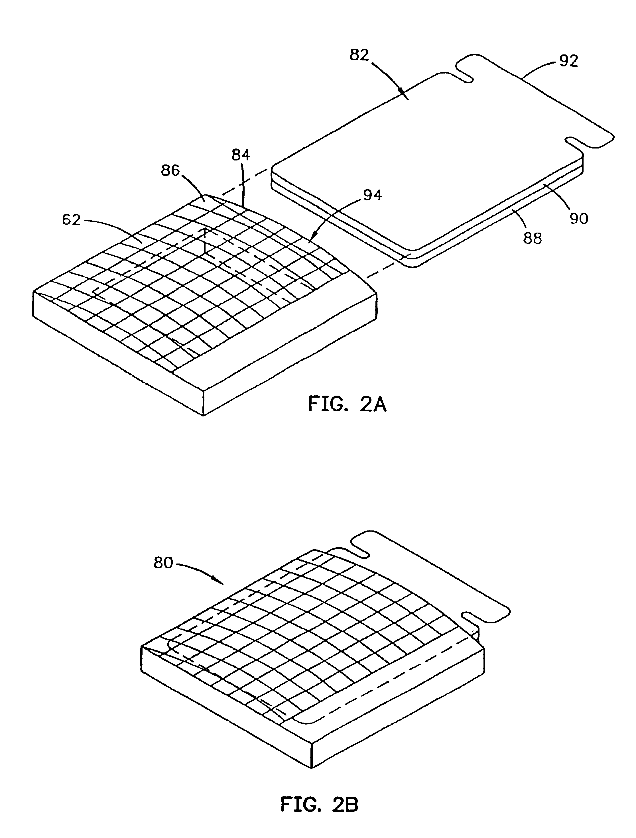
[0088]The present invention is directed to a non-contact wound covering for controlling the local environment at a wound site on a patient. A wound site includes those portions of the patient's skin obviously definable as the wound area and the immediately adjacent periwound area as the selected treatment area of the wound site. The wound covering protects the wound from contamination by materials from the outside environment and also prevents the wound site from shedding contaminants into the local environment of the patient, i.e. the hospital room. The treatment volume formed proximate the wound site can be controlled to create an optimal healing environment. The word “wound” as used herein refers generically to surgical incisions, ulcers, or other lesions or breaks in the skin.

[0089]First, a substantially vertical wall is provided to encircle the selected treatment area on the surface of the patient's skin. This vertical wall provides an upper surface to support a layer spanning ...


PUM


Abstract

An apparatus for treating tissue in a tissue treatment area includes a heater that does not contact the tissue. The apparatus may be attached to the skin of a person to form a treatment volume about the tissue to be treated. The heater, supported at the layer, is held near the tissue to be treated, out of contact with the tissue. The apparatus includes a controller to cause the heater to raise the temperature of tissue in the tissue treatment area to a temperature in a range from a pretreatment temperature to 38° C. The controller may include means that cause the heater to operate over a therapeutic sequence, that cycle the heater on and off, that provide selectable average temperature values, that cause the heater to operate over an average temperature range, that cause the heater to operate at an average temperature over a therapy cycle, or that cause the heater to operate at an average temperature over a therapeutic sequence.

Description

CROSS REFERENCES TO RELATED CO-PENDING APPLICATIONS[0001]This application is a continuation application of U.S. patent application Ser. No. 09 / 778,590, filed on Feb. 7, 2001, now U.S. Pat. No. 6,423,018 which is a continuation of U.S. patent application Ser. No. 09 / 491,722, filed Jan. 27, 2000, now U.S. Pat. No. 6,213,966, which is a continuation of U.S. patent application Ser. No. 09 / 271,822, filed Mar. 18, 1999, now U.S. Pat. No. 6,113,561, which is a continuation of U.S. patent application Ser. No. 08 / 786,713, filed Jan. 21, 1997, now U.S. Pat. No. 5,964,723, which is a continuation-in-part U.S. patent application Ser. No. 08 / 356,325, filed Feb. 21, 1995, now abandoned, which is a 35 U.S.C. 371 priority application of PCT International Application Serial No. PCT / US93 / 05876, filed Jun. 18, 1993, which is a continuation-in-part of, and claims priority from, U.S. Pat. application Ser. No. 07 / 900,656, filed Jun. 19, 1992, now abandoned.[0002]This application is related to the followi...

Claims


Application Information

Patent Timeline
Patent Type & Authority Patents(United States)
IPC IPC(8): A61F13/00A61F5/00A61F7/00A61F7/02A61F7/03A61F7/08A61F7/12A61F13/02A61F15/00A61M1/00A61M3/02
CPCA61F7/007A61F7/02A61F7/03A61F13/023A61M1/0084A61M3/0283A61M35/00A61F2007/0001A61F2007/006A61F2007/0062A61F2007/0086A61F2007/0091A61F2007/0095A61F2007/0226A61F2007/0255A61F2007/0295A61F2013/0017A61F2013/00174A61F2013/00187A61F2013/00195A61F2013/002A61F2013/00212A61F2013/0057A61F2013/00825A61F2013/00834A61F2013/00846A61F2013/00851A61F2013/00868A61F2013/00872A61F2013/00906A61F2013/0091A61F2013/00919A61F2013/00944A61F2013/00953A61M1/85
Inventor AUGUSTINE, SCOTT D.
Owner 3M INNOVATIVE PROPERTIES CO
Why Eureka
Try Eureka